How to Ensure Carbon Steel Pipe Cap Welding Compatibility
Welding a pipe cap to a carbon steel pipe may look straightforward, but a reliable connection depends on more than simply selecting a welding machine and filler wire. The material grade, wall thickness, joint preparation, welding procedure, preheating requirements, and inspection criteria all influence the final result. For buyers and engineers sourcing carbon steel pipe caps, welding compatibility should therefore be evaluated before fabrication rather than after a weld has already failed inspection.
This is especially relevant for process pipes, petrochemical plants, power plants, and other industrial systems where welded fittings may be subject to pressure, temperature variations, vibration, or multiple heat cycles. Such a cap may be of an incorrect grade or may be welded by an untrained process. This may lead to issues such as lack of fusion, excessive hardness, hydrogen cracking, deformation, or premature leaking.
The first step in a practical compatibility evaluation is to determine the specific material of the pipe and the cap. Wrought carbon steel pressure fittings are often made from ASTM A234 WPB, but the exact welding method is still dependent on the whole project's requirements. A similar idea may be used in the case of other carbon and low-alloy steel grades. The material certificate, thickness, service conditions, welding code, and certified WPS should be considered by engineers before deciding on how to make the connection.
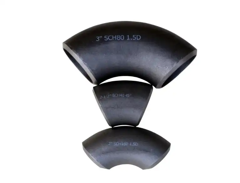
Dimensional compatibility is another factor of the welding equation, particularly for carbon steel pipe caps. A cap is available in sizes from tiny process connections to big diameter pipelines and wall thicknesses from schedules such as Sch10 to Sch160. More critical are joint fit-up, heat input, preheat, distortion control, and inspection requirements as the diameter and wall thickness grow.
Start with Material and Joint Compatibility
Make sure you know precisely what materials are being bonded before you pick a welding procedure. This seems simple yet one of the most crucial stages in avoiding welding difficulties.
Verify the Pipe Cap Grade Before Welding
The material designation on the purchase order needs to conform to the material identification on the product and the matching material certificate. ASTM A234 WPB is a typical specification for carbon steel pressure fittings, including pipe caps. However, the WPB designation alone does not specify the whole welding technique.
The pipe grade should also be inspected. The fact that a carbon steel cap is being welded on a pipe does not entail that a generic carbon steel welding process is being used. The selection of filler metal and welding settings may be influenced by variations in chemical composition, thickness, strength requirements, or service temperature.
The material test certificate is, therefore, not only a document for filing for procurement projects. This offers the engineering team the data they need to validate the fitting is within the material group of the certified welding technique.
Compare thickness, diameter, and joint geometry
The welding situation depends directly on the pipe diameter and wall thickness. A thin-wall connection may lose heat fast and may be more vulnerable to burn-through if the heat is high, whereas a heavy-wall junction normally needs more consideration of heat input, preheat, interpass temperature, and the number of welding passes.
The larger the size of the components, the more critical the fit-up. The pipe and cap shall be aligned according to the authorized joint design with control of the root opening, bevel angle, and internal alignment within relevant fabrication criteria.
A poor fit-up of carbon steel pipe caps requires the welder to adjust by modifying arc length, travel speed, or heat input. This may mean less consistency in the welding process and a higher potential for faults.

Choose the Welding Process According to the Application
No one welding procedure is inherently suited for every carbon steel pipe cap. All three may be utilized for carbon steel fabrication; however, the actual benefits of each vary by joint, manufacturing environment, thickness, and needed weld quality.
When SMAW Is a Practical Choice?
Shielded metal arc welding (SMAW) remains popular for field fabrication, maintenance, and installation since the equipment is quite portable and does not need an external source of shielding gas. This may be especially beneficial in situations where pipe caps need to be welded in areas where access or environmental conditions are not as amenable to mechanical methods.
Where carbon steel work is involved, low-hydrogen electrodes such as E7018 are often employed. But the electrode should not be picked only because it is popular. Its categorization and deposited weld-metal qualities should be in accordance with the authorized welding technique and with the specifications of the base materials.
Low-hydrogen electrodes must also be kept dry. Electrodes should be stored and handled in accordance with the manufacturer’s guidelines and the appropriate welding process. Contaminated or incorrectly managed consumables might jeopardize the very hydrogen management technique they are meant to deliver.
Where GTAW Provides Better Control?
GTAW or TIG (Gas Tungsten Arc Welding) provides the welder excellent control of the arc and weld pool. This makes it especially effective when quality of roots and control of penetration are critical.
ER70S-2 or ER70S-6 are appropriate filler wires for carbon steel applications; however, the final choice must be guided by the qualified WPS and not a general guideline. Argon is often utilized as the shield gas, with certain applications requiring further consideration for root protection.
GTAW is particularly well suited for thin-wall components and essential root passes. It usually creates a cleaner weld with less spatter than SMAW but may not be the most affordable method when a big amount of weld metal must be placed.
When GMAW Makes Sense for Production?
For fabrication settings that need productivity and repeatability, gas metal arc welding, or GMAW, is often appealing. Continuous wire feeding may lay down more material than many manual techniques, saving time on repeated welding jobs.
Solid wires like ER70S-6 may be used to weld carbon steel pipe caps where the material and method allow. Argon/CO₂ mixes are typical for welding carbon steel with GMAW; however, the precise gas mix should be chosen based on the welding process and the desired arc characteristics.
GMAW may provide a viable trade-off between deposition velocity and weld quality for high-volume manufacturing. The procedure requires shielding gas and a more regulated equipment setup and hence is less convenient than SMAW in certain distant field circumstances.
Select filler metal from the approved welding procedure
Filler metal selection for carbon steel pipe caps should be based on the actual materials to be connected and the mechanical requirements of the completed connection. A filler that has a recognizable categorization is not enough; compatibility is not created that way.
Match Strength and Chemistry Without Overlooking the Code
The filler metal should provide appropriate deposited weld-metal characteristics for the base materials and service requirements. Many carbon steel applications employ ER70S-series wires or E70-series electrodes; however, the specific consumable depends on the certified technique.
Before manufacturing, the engineers should evaluate the welding technique specification and the material certifications. The pipe and cap being of various material classes may demand a more carefully selected consumable than for a same-grade junction.
This is especially significant if the pipe system is designed for impact toughness, high-temperature service, or other mechanical requirements. A filler that seems acceptable on the basis of tensile strength alone may not meet the whole project's requirements.
Consider Hydrogen Control for Restrained Joints
Hydrogen cracking may occur in certain welds of carbon and low-alloy steels, especially when there is a combination of vulnerable materials, hydrogen, high constraint, and adverse cooling conditions. For thick members and very constrained joints, more considerations are necessary.
The practical answer may include low hydrogen consumables, regulated preheat, correct interpass temperature, clean joint surfaces, and proper consumable storage. Such safeguards should be included in the certified welding technique and not as informal shop practices.
Account for Thickness and Production Conditions
A welding process that works well for a relatively thin cap may not work directly on a heavy-wall component. You may need to alter the heat input, travel speed, number of passes, preheat, and interpass temperature.
Welding a Sch10 part, for example, is not the same as welding a strong wall Sch160 fitting. The bigger joint may need many passes and stricter heat control, while a thinner portion may need more attention to avoid overpenetration or deformation.
That’s why the welding technique should specify the qualifying thickness range and not assume that one set of parameters covers all sizes of carbon steel pipe caps.
Prepare the Joint Before Applying Heat
Many weld defects originate before the arc is struck. Good welding preparation gives the welder a stable starting point and reduces the need to compensate for poor fit-up during welding.
Remove Contamination from the Welding Area
Oil, grease, moisture, loose scale, rust, paint, and other contaminants should be removed from the bevel and adjacent surfaces according to the applicable fabrication procedure. Carbon steel surfaces can appear visually clean while still carrying contaminants that affect arc stability or introduce hydrogen and other sources of weld defects.
The cap and pipe should also be checked for correct alignment. The bevel geometry and root opening should correspond to the approved joint design. If the components do not fit correctly, forcing them into position can introduce residual stress before welding even begins.
Control Preheat for Thicker Sections
Preheating is not automatically required for every carbon steel pipe cap, but it can be important for thicker or more crack-sensitive materials. Raising the temperature of the material before welding can slow the cooling rate and help reduce the conditions associated with hydrogen-assisted cracking.
The required preheat temperature should come from the applicable welding procedure or governing code. It should not be chosen solely from a generic temperature table without considering the material and joint conditions.
During welding, the interpass temperature should also remain within the range specified by the procedure. Excessive heat can be just as undesirable as insufficient heat, particularly where mechanical properties or distortion control are important.
Know When PWHT Is Required
Post-weld heat treatment, commonly called PWHT, may be required for certain pressure piping applications, material grades, thicknesses, or service conditions, including systems that use carbon steel pipe caps. Its purpose and requirements should be established from the governing code and project specification.
Do Not Treat PWHT as a Universal Requirement
Some carbon steel welds do not require PWHT, while others may be subject to mandatory heat treatment requirements. Factors such as material group, nominal thickness, design conditions, applicable construction code, and service requirements can affect the decision.
For that reason, a general statement such as “carbon steel pipe caps require PWHT” would be misleading. The correct question is whether the particular welded joint falls within the PWHT requirements of the applicable code and qualified procedure.
Where PWHT is required, the procedure should define the heating rate, holding temperature, soaking time, cooling conditions, and temperature-monitoring method. These parameters should be documented and controlled rather than estimated during fabrication.
Consider the Effect on the Finished Joint
Heat treatment can change the residual stress state and mechanical characteristics of the weld and heat-affected zone. It can also introduce additional dimensional considerations for large or thin components.
For projects governed by ASME B31.3 or another piping code, the engineering team should confirm the applicable PWHT provisions rather than applying a generic temperature range. The material specification and qualified welding procedure should be reviewed together before production starts.
Verify the Weld with Appropriate Inspection
Welding compatibility is not fully demonstrated simply because a weld looks acceptable. Inspection provides evidence that the completed joint meets the specified acceptance criteria.
Start with a visual examination.
Visual inspection is usually the first stage of weld examination. Inspectors can evaluate the weld profile, visible cracks, undercut, overlap, surface porosity, arc strikes, and other visible conditions.
Dimensional checks can also confirm whether the cap remains properly aligned and whether the finished joint meets the fabrication requirements. Early visual inspection is valuable because obvious problems can be corrected before more expensive examination methods are performed.
Use NDT According to Joint Requirements
Non-destructive testing may include radiographic testing, ultrasonic testing, magnetic particle testing, or other techniques depending on the material, joint configuration, thickness, code, and project specification.
Radiographic or ultrasonic examination can provide information about internal discontinuities that cannot be identified reliably from the outside surface. Magnetic particle testing is useful for detecting certain surface and near-surface discontinuities in ferromagnetic carbon steel.
The objective is not to perform every possible inspection method. Instead, the inspection plan should use the techniques required by the governing specification and the risk level of the piping service.
Keep Inspection Records Traceable
For industrial procurement, inspection documentation is part of product quality. Material certificates, welding records, NDT reports, heat-treatment records where applicable, and dimensional inspection results should be traceable to the relevant components and project requirements.
This documentation becomes particularly valuable when a buyer needs to demonstrate compliance during commissioning, maintenance, or future audits. A supplier that can provide clear and consistent quality records offers more than the physical fitting itself; it reduces uncertainty throughout the project lifecycle.
Conclusion
Ensuring welding compatibility for carbon steel pipe caps requires more than selecting a commonly used electrode or welding process. The pipe and cap materials must first be identified and matched with the applicable design and welding requirements. Diameter, wall thickness, joint geometry, service conditions, and production environment should then be considered when selecting the welding process and filler metal.
SMAW, GTAW, and GMAW can each be appropriate for carbon steel applications, but their suitability depends on the specific joint and qualified welding procedure. Surface preparation, preheat, interpass temperature control, and hydrogen management can further influence weld quality, particularly for thicker or more highly restrained joints. PWHT should likewise be determined from the applicable code and project requirements rather than treated as a universal step.
For buyers, the evaluation should continue beyond the physical appearance of the fitting. Material certificates, dimensional accuracy, welding compatibility, NDT requirements, traceability, and supplier documentation all contribute to a reliable procurement decision. Choosing carbon steel pipe caps from a manufacturer that can support these technical and quality requirements helps reduce fit-up issues, inspection failures, and avoidable delays during fabrication and installation.
For more information or assistance with your carbon steel pipe cap welding needs, please contact us at oudi-04@oudiguandao.com.
References
1. Smith, J. R. (2018). Advanced Welding Techniques for Carbon Steel Pipe Caps. Journal of Welding Technology, 42(3), 215-228.
2. Johnson, M. K., & Brown, L. A. (2019). Filler Material Selection for Carbon Steel Pipe Welding: A Comprehensive Guide. International Journal of Metallurgy, 55(2), 178-195.
3. Thompson, R. D. (2020). Post-Weld Heat Treatment Optimization for Carbon Steel Pipe Caps. Journal of Materials Engineering and Performance, 29(8), 5123-5137.
4. Anderson, S. L., & Wilson, P. J. (2017). Non-Destructive Testing Methods for Carbon Steel Pipe Welds: A Comparative Study. NDT & E International, 89, 114-126.
5. Lee, C. H., & Park, J. Y. (2021). Effect of Welding Parameters on the Mechanical Properties of Carbon Steel Pipe Cap Joints. Welding in the World, 65(5), 897-910.
6. Garcia, M. R., & Martinez, E. S. (2019). Surface Preparation Techniques for Carbon Steel Pipe Cap Welding: Influence on Weld Quality. Journal of Manufacturing Processes, 38, 395-408.

Need help finding the right solution with our experts. Please contact us.

SINCE 1998 Your Reliable Pipeline Manufacturer