How to Match Pipe Tees with Elbows, Reducers, and Flanges?
Matching pipe tees with elbows, reducers, and flanges is not simply a matter of choosing fittings with the same nominal pipe size. For a pipeline connection you also have to consider the type of tee, outside diameter of pipe, wall thickness, material, pressure and temperature conditions, method of connection, and dimensional requirements. Missing these aspects might result in components that seem to match on paper but cause issues later in manufacture or installation. A pipe tee is often utilized when a pipeline has to divide or combine flow with another line. An elbow alters the direction of the pipe, a reducer joins two pipes of various diameters, and a flange is a removable connection point for equipment, valves, or another flanged part. All these fittings generally function together in the same pipe assembly. Therefore, the dimensions and design requirements of these fittings need to be evaluated as a system instead of individual components. The aim for engineers, fabricators, and buying teams is to develop an association that can be built properly, installed without major change, and operated under its specified service conditions. By considering the following, the selection process may be made more practical, and compatibility difficulties can be reduced before the fittings arrive on the project site.
Start with the piping configuration and connection requirements
Determine Whether the Tee Is Equal or Reducing
The first choice is to figure out what kind of tee the piping configuration truly needs. An equal tee has the same nominal size at the run and branch. A decreasing tree has a smaller branch or other outlet decreased. This difference determines how the tee must be linked to the remainder of the piping system.
An equal tee, for example, may be useful if the main line and its branch have the same pipe size. A reducing tee may remove the requirement for a separate reducer if a smaller instrument, process line, or distribution branch departs the main pipeline occasionally. In various layouts the reducer may be after the normal tee. With this, the transition in size has to be farther downstream.
This is critical when you are connecting a tee with an elbow or flange. The fitting arrangement should be made to the actual pipe dimensions as given on the design, not presuming that each component should be the same nominal size. A decreasing tee with a reducer and subsequently a flange may be completely acceptable if the design requires a gradual or regulated shift in size.
Check the End Dimensions Before Ordering
Nominal pipe size alone is not enough information to make a reliable match. The true outer diameter, wall thickness, end preparation, and dimensional standard should be verified.
For butt weld fittings, the ends of the fitting should be compatible with the size and the relevant fitting standard. Even if the nominal dimension is accurate, differences in wall thickness or weld-end shape might cause extra manufacturing effort.
This is especially the case if a number of fittings are fitted in succession. A tee may be connected to an elbow on one side and a reducer or pipe section on the other, and the branch may end at a flange. Each connection should be examined on its own, but the whole assembly should be tested to make sure the components will fit in the given area.
Confirm the Applicable Fitting and Piping Standards
Standards offer common dimensions and a production platform, but application and kind of fitting determine the appropriate standard. ASME B16.9, for example, is a common standard for factory-made wrought butt welding fittings, and material requirements may be met by standards such as ASTM A234 for carbon and alloy steel fittings.
The crucial thing is not to choose a standard because it is familiar. The project specification, pipe class, service circumstances, and geographical requirements should establish which standards are relevant. The tee, elbow, reducer, flange, and pipe should be chosen in a suitable specification framework.
The supplier should also be able to offer dimension information and material documents on request. This offers the buying team a stronger base for determining if the fitting offered complies with the technical requirements before manufacture or shipping.

Match Pipe Tees with Elbows and Reducers as One Assembly
Position the Elbow According to Flow Direction
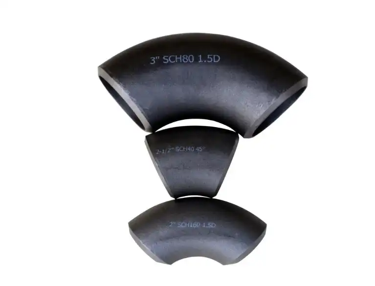
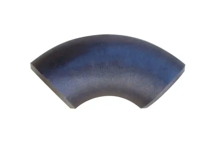
Elbows and pipe tees have various roles; thus, their connection should be looked at from the point of view of the pipe architecture. The tee makes the branch. The elbow changes the flow direction. Thus, their orientation may influence both the installation area and the direction of the branch line.
A typical error is to just verify that the sizes of the connector ends are the same. Two fittings may join physically and yet make an uncomfortable routing configuration. This might lead to difficulty in welding, limit inspection access, or cause undue stress on the pipe.
Before fabrication, the alignment of the tee branch and elbow should be verified against the pipe design or 3D model. This is particularly essential in close pipe assemblies where a little change in the elbow orientation might impact the position of a valve, flange, support, or equipment.
Use Reducers for Planned Size Transitions
Reducers are used to move from one nominal size to another in a pipe system. If a reducer is put at or near a tee, the bigger and smaller ends must match the planned pipe or fitting diameters.
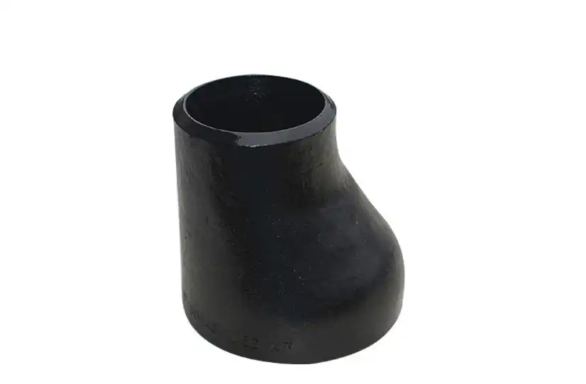
The choice between concentric and eccentric reducers also relies on the service and piping layout. A concentric reducer maintains the centerline straight, whereas an eccentric reducer moves the centerline. In certain horizontal pipe applications, the orientation of an eccentric reducer might be critical for draining, venting, or maintaining the appropriate flow pattern.
The reducer should not be chosen only because its nominal sizes match those of the tee. Engineers also have to take into account wall thickness, material, pressure and temperature conditions, and specifications of the pipe standard in use.
A nicely matched tee and reducer may help manufacturing as well. If the tee’s branch already has the needed reduced outlet, then it may not be necessary to install another reducer. However, if you need to change sizes at a certain point in your pipe design, then a dedicated reducer might provide you more flexibility.
Consider Flow and Installation Space Together
The quickest link isn’t always the greatest connection. Technically, a tee, elbow, and reducer may be joined together, but the overall size might be problematic when located near pumps, valves, vessels, or other fittings.
Therefore, the engineers should check the center-to-end dimensions, face-to-face dimensions when relevant, and room for welding and inspection. The design should also provide sufficient access for equipment and staff during installation.
This is especially true with prefabricated pipework. What may appear like a straightforward connection on a design might be difficult to install if fittings are not oriented properly or if there is not enough access around the welds. Before fabrication, check the whole assembly to save costly rework later.
Make Flange Connections Compatible with the Tee Assembly
Verify Flange Size, Rating, and Facing
When a branch from a tee does become connected to equipment or any other flanged component, the flange has to be chosen by more than nominal pipe size. Consideration should be given to the flange size, pressure class, material, face, bore, and dimensional standard.
For example, a flange may have the proper nominal size yet have the wrong pressure class or facing for the mating part. The gasket and bolting arrangement must also be consistent with the service circumstances and with the flange configuration in a flange connection.
The flange bore should also be checked if it is to be welded to a pipe or fitting with a precise wall thickness. We want to have a nice transition without any inadvertent constraint or manufacturing problem.
Keep the Flange and Piping Materials Compatible
Material compatibility is important all throughout the assembly, not only at the tee. A carbon steel tee mated to a carbon steel pipe and flange may be simple enough, but more complicated systems might have various alloys, corrosion-resistant materials, or unique service needs.
The material of pipe tees should be chosen for compatibility with the fluid conveyed, the working temperature, pressure, corrosion environment, and welding requirements. If different materials are involved, the optimal connecting process and material combination should be determined by the technical requirements, rather than by visual similarities.
Material traceability is also useful for industrial undertakings. Mill certifications, material test results, and other quality documentation may be used to certify that the provided fittings are compliant with the stated material grade.
Check Bolt Holes and Flange Orientation
Another issue that may easily be missed during construction is flange orientation. The flange must be positioned such that the bolt holes in the flange match the bolt holes in the mating flange and the equipment being connected.
Valve access, instrument positioning, and maintenance clearance may also be affected by the orientation of a flange on a tee branch. After welding, it may be necessary to cut and re-fabricate to correct the orientation; therefore, it is best to check the arrangement before permanently assembling the fitting.
Flange orientation of prefabricated pipe spools should be confirmed against the fabrication design before welding. This simple procedure may avoid complications during transit of the spool to the installation location.
Control Alignment During Fabrication and Installation
Mark the Tee Branch Before Tack Welding
Accurate layout is essential when a tee is connected with elbows, reducers, and flanges. Before tack welding, fabricators should verify the centerlines, branch direction, orientation, and required dimensions against the approved drawing.
The branch outlet should be positioned according to the intended flow path and connected piping. If the tee is rotated even slightly from its specified orientation, the downstream elbow or flange may no longer line up correctly.
Temporary alignment tools and clamps can help hold components in position during fitting. However, these tools should support the approved fabrication procedure rather than replace dimensional inspection.
Follow the Qualified Welding Procedure
For butt weld assemblies, welding should be performed according to the applicable welding procedure and project requirements. The procedure may specify the welding process, filler material, preheat requirements, interpass temperature, joint preparation, and post-weld heat treatment where applicable.
GTAW and SMAW are both used in industrial pipe fabrication, but the appropriate process depends on the material, thickness, service, project specification, and qualified welding procedure. The same welding approach should not automatically be applied to every pipe tee or fitting.
Tack welds also need to be properly placed and controlled because poor fit-up can contribute to distortion or dimensional problems. After welding, the finished assembly may require visual inspection and, depending on the service and specification, nondestructive examination such as radiographic or ultrasonic testing.
Avoid Forcing Components into Position
One practical rule during fitting is that components should not be forced into alignment simply because their nominal dimensions appear correct. Excessive force can introduce stress into the piping assembly and make the final connection difficult to inspect or maintain.
If a tee, elbow, reducer, or flange does not align as expected, the cause should be identified before welding continues. The issue may come from incorrect dimensions, an orientation error, thermal distortion, or a mismatch between the drawing and the supplied component.
Taking time to correct the fit-up of pipe tees before completing the weld is usually much less costly than repairing a completed spool.
Verify Pressure, Temperature, and Material Requirements
Evaluate the Complete Pressure Boundary
The pressure rating of a piping connection should be evaluated as a complete pressure boundary. Looking at the pressure rating of the tee alone is not enough because the pipe, elbow, reducer, flange, gasket, bolting, and other connected components also have to meet the design requirements.
Material grade, wall thickness, fitting dimensions, design temperature, and applicable pressure class can all affect the allowable operating conditions. The weakest component or connection detail can determine the practical limitation of the assembly.
For this reason, procurement documents should contain enough information for the supplier to identify the correct fitting configuration rather than simply stating “carbon steel tee” or “stainless steel tee.”
Consider the Actual Service Conditions
The fluid flowing through the piping system also matters. Water service, steam, hydrocarbons, corrosive chemicals, and other process media can place very different demands on the same fitting.
Temperature cycling, corrosion, erosion, vibration, and external loads may need to be considered depending on the application. In critical systems, the piping design should address these conditions through the applicable engineering codes and project specifications.
This is where a technically experienced supplier can add value. Instead of treating the tee as an isolated commodity, the supplier can review the requested material, dimensions, standard, and connection requirements and identify obvious inconsistencies before manufacturing.
Conclusion
Matching pipe tees with elbows, reducers, and flanges requires more than checking whether the nominal sizes appear to be the same. A reliable connection starts with the correct tee configuration and continues with careful checks of outside diameter, wall thickness, material, pressure and temperature requirements, connection type, flange details, and applicable standards.
The relationship between the fittings also matters. An elbow must be oriented correctly for the intended pipe route, a reducer needs to provide the required size transition, and a flange must match its mating component in size, rating, facing, and connection requirements. During fabrication, accurate fit-up and qualified welding procedures help prevent alignment and distortion problems, while inspection and pressure testing provide additional assurance before the system enters service.
For purchasing teams, providing complete specifications is one of the simplest ways to avoid compatibility problems. When the tee type, dimensions, material grade, standard, quantity, and service conditions are clearly defined, manufacturers can respond more accurately and reduce the chance of costly modifications at the installation site. Cangzhou Oudi Pipe Manufacture Co., Ltd. has supplied carbon steel pipe fittings, valves, and flanges since 1998, serving customers in different international markets. For projects that require coordinated fittings, working with a manufacturer that understands the relationship between tees, elbows, reducers, and flanges can make the procurement and installation process considerably more efficient. They are dedicated to quality and customer satisfaction. For more information or inquiries, please contact us at oudi-04@oudiguandao.com.
FAQ
1. What are the most common materials used for pipe tees?
The most common materials for pipe tees are carbon steel, stainless steel, and alloy steel, each suited for different applications based on factors like corrosion resistance and pressure requirements.
2. How do I ensure size compatibility when matching pipe tees with other fittings?
To ensure size compatibility, consider the nominal pipe size (NPS), outside diameter (OD), and wall thickness of all components, using reducers when necessary to connect different sizes.
3. What tools are essential for proper alignment during pipe tee installation?
Essential alignment tools include pipe alignment clamps, laser alignment tools, and spirit levels to ensure accurate positioning and orientation of pipe tees and other fittings.
4. How often should pipe tees be inspected in a piping system?
The inspection frequency depends on the application and operating conditions, but generally, a comprehensive inspection should be performed at least annually, with more frequent visual checks.
References
1. Smith, J. (2019). Piping Systems: Design and Installation. New York: Engineering Press.
2. Johnson, R. (2020). Advanced Techniques in Pipe Fitting and Alignment. Chicago: Industrial Publishing.
3. Brown, M. (2018). Materials Selection for Piping Components. London: Technical Publications Ltd.
4. Davis, A. (2021). Maintenance and Inspection of Industrial Piping Systems. Houston: Oil & Gas Industry Press.
5. Wilson, T. (2017). Pressure Ratings and Temperature Limits in Piping Design. Toronto: Engineering Solutions Inc.
6. Thompson, L. (2022). Best Practices for Documenting Piping System Maintenance. San Francisco: Industrial Management Association.

Need help finding the right solution with our experts. Please contact us.

SINCE 1998 Your Reliable Pipeline Manufacturer