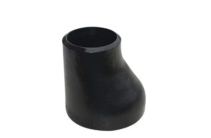
How to size a concentric reducer from 4 to 2-inch Sch 40 for a piping system?
Measuring a concentric reducer from 4 to 2-inch Plan 40 for a channeling framework is a pivotal assignment in different mechanical applications. This handle requires cautious thought of different variables to guarantee ideal execution and proficiency. Concentric reducers play a imperative part in transitioning between diverse pipe sizes whereas keeping up appropriate stream characteristics. When managing with carbon steel elbows and other components in a channeling framework, it's fundamental to get it the complexities of measuring reducers accurately. This web journal post will dive into the key viewpoints of measuring a concentric reducer, investigating the vital steps, calculations, and contemplations to accomplish the best comes about for your channeling framework. By taking after the rules displayed here, you'll be able to make educated choices and guarantee the consistent integration of your 4 to 2-inch Plan 40 concentric reducer.

What are the key factors to consider when sizing a concentric reducer?
Flow rate and pressure drop
When measuring a concentric reducer from 4 to 2-inch Plan 40 for a channeling framework, one of the essential variables to consider is the stream rate and weight drop. These components are vital in deciding the generally execution of the framework, particularly when joining carbon steel elbows and other fittings. The stream rate straightforwardly impacts the speed of the liquid passing through the reducer, which in turn influences the weight drop over the fitting. It's basic to calculate the anticipated stream rate and guarantee that the chosen reducer can handle it without causing intemperate turbulence or weight misfortune. Furthermore, the weight drop over the reducer ought to be inside worthy limits to keep up framework proficiency. Carbon steel elbows associated to the reducer may moreover contribute to weight drops, so their affect must be calculated into the in general calculations.
Material compatibility and corrosion resistance
Another basic viewpoint to consider when measuring a concentric reducer is fabric compatibility and erosion resistance. The reducer must be made of a fabric that is consistent with the liquid being transported and can withstand the working conditions of the channeling framework. Carbon steel elbows and other components in the framework ought to too be taken into account when selecting the reducer fabric. Erosion resistance is especially vital in situations where the liquid or outside variables may cause corruption of the reducer over time. It's pivotal to select a fabric that can keep up its astuteness and execution all through the system's life expectancy. A few applications may require specialized coatings or combinations to upgrade erosion resistance, particularly when managing with forceful liquids or cruel environments.
Temperature and thermal expansion
Temperature and warm development are imperative contemplations when measuring a concentric reducer for a channeling framework. The working temperature of the liquid and the surrounding temperature can altogether affect the execution and life span of the reducer. Tall temperatures may cause warm extension, which can lead to stretch on the reducer and associated components, counting carbon steel elbows. It's basic to account for these warm impacts when selecting and introducing the reducer to anticipate spills, distortion, or disappointment. Moreover, temperature vacillations can influence the fabric properties of the reducer and encompassing components, possibly changing their execution characteristics. Legitimate cover and development joints may be essential to relieve the impacts of temperature changes and guarantee the life span of the channeling system.
How does the reducer's angle affect system performance?
Impact on fluid velocity and turbulence
The point of a concentric reducer plays a noteworthy part in deciding the system's execution, especially in terms of liquid speed and turbulence. A legitimately measured reducer with an fitting point makes a difference keep up smooth stream moves between the bigger and littler pipe segments. This is particularly vital when considering the interaction between the reducer and associated carbon steel elbows. A continuous decrease in distance across minimizes the chances of stream division and turbulence, which can lead to weight drops and decreased proficiency. The point of the reducer influences the speed profile of the liquid as it passes through, impacting the generally water powered execution of the framework. It's pivotal to select a reducer point that equalizations the require for compact plan with ideal stream characteristics to guarantee the best conceivable execution in your channeling system.
Stress distribution and structural integrity
The point of a concentric reducer moreover has a critical affect on stretch conveyance and basic keenness inside the channeling framework. A well-designed reducer makes a difference disperse the stresses equitably over its surface, diminishing the chance of localized stretch concentrations that seem lead to disappointment. This is especially vital when considering the association focuses between the reducer and carbon steel elbows or other fittings. The point of the reducer influences how strengths are transmitted through the framework, impacting the generally basic solidness. A progressive lessening in breadth ordinarily comes about in way better push dispersion compared to a soak point, which can make zones of tall stretch. Appropriate measuring and choice of the reducer point are basic for keeping up the long-term judgment of the channeling framework and anticipating untimely wear or disappointment of components.
Installation and maintenance considerations
The point of a concentric reducer has vital suggestions for establishment and support forms in a channeling framework. A well-chosen point can encourage less demanding establishment, especially in tight spaces or complex channeling formats. This is particularly significant when working with carbon steel elbows and other fittings that may have particular space necessities. The reducer's point can influence the ease of get to for upkeep and assessment exercises, possibly affecting the in general lifecycle costs of the framework. A slow point may permit for superior visual review and cleaning of the inside surfaces, whereas a more extreme point might require specialized apparatuses or strategies for upkeep. Moreover, the point of the reducer can impact the system's capacity to be adjusted or extended in the future, making it an imperative thought for long-term arranging and adaptability in mechanical applications.
What are the best practices for installing a 4 to 2-inch concentric reducer?
Proper alignment and support
When introducing a 4 to 2-inch concentric reducer in a channeling framework, legitimate arrangement and back are vital for guaranteeing ideal execution and life span. The reducer ought to be carefully adjusted with the interfacing channels and carbon steel elbows to minimize push on the joints and anticipate spills. Utilizing fitting pipe bolsters and holders makes a difference convey the weight equitably and avoids listing or misalignment over time. It's basic to consider the impacts of warm extension and withdrawal, especially in frameworks with critical temperature variances. Legitimate bolster arrangement can offer assistance oblige these developments and diminish the hazard of harm to the reducer and associated components. Also, guaranteeing that the reducer is introduced with the redress introduction is imperative for keeping up the expecting stream characteristics and anticipating issues such as discuss pockets or silt accumulation.
Sealing and connection methods
Selecting the appropriate sealing and connection methods is critical when installing a 4 to 2-inch concentric reducer. The choice of gaskets, flanges, or welding techniques depends on factors such as operating pressure, temperature, and the specific requirements of the piping system. When connecting the reducer to carbon steel elbows or other fittings, it's essential to use compatible materials and follow industry standards for joint preparation and assembly. Proper torquing of bolted connections and adherence to welding procedures are crucial for preventing leaks and ensuring the integrity of the system. In some cases, specialized sealing compounds or techniques may be necessary to accommodate specific fluid properties or environmental conditions. Regular inspection and maintenance of these connections are essential for identifying and addressing potential issues before they lead to system failures or safety hazards.
Testing and quality assurance
Thorough testing and quality assurance procedures are essential when installing a 4 to 2-inch concentric reducer in a piping system. Pressure testing should be conducted to verify the integrity of the connections and ensure that there are no leaks at the reducer or adjoining carbon steel elbows. Non-destructive testing methods, such as radiography or ultrasonic inspection, may be employed to check for internal defects or improper welds. It's important to follow industry standards and local regulations for testing procedures and documentation. Quality assurance measures should include verifying the material certifications, dimensions, and surface finish of the reducer and connected components. Proper documentation of installation procedures, test results, and any issues encountered during the process is crucial for maintaining a comprehensive record of the system's history and facilitating future maintenance or troubleshooting activities.
Conclusion
Sizing and installing a concentric reducer from 4 to 2-inch Schedule 40 for a piping system requires careful consideration of various factors. From flow characteristics and material selection to installation techniques and quality assurance, each aspect plays a crucial role in ensuring optimal performance and longevity. By following best practices and considering the interaction between the reducer and other components like carbon steel elbows, engineers and technicians can create efficient and reliable piping systems. As industrial applications continue to evolve, the importance of proper reducer sizing and installation remains paramount in maintaining safe and effective operations across various industries.
For more information on our high-quality carbon steel pipe fittings, valves, and flanges, please contact us at oudi-04@oudiguandao.com. Since 1998, Cangzhou Oudi Pipe Manufacture Co., Ltd. has been a leading manufacturer in China, providing exceptional products and services to customers worldwide.
FAQ
Q: What is the purpose of a concentric reducer in a piping system?
A: A concentric reducer is used to transition between pipes of different diameters while maintaining a centered flow path, helping to maintain proper flow characteristics and minimize pressure drops.
Q: How does the angle of a concentric reducer affect fluid flow?
A: The angle of a concentric reducer impacts fluid velocity and turbulence. A gradual angle typically results in smoother flow transitions and less turbulence compared to a steeper angle.
Q: What materials are commonly used for concentric reducers?
A: Common materials include carbon steel, stainless steel, and various alloys, depending on the specific application requirements and fluid properties.
Q: How often should concentric reducers be inspected?
A: Inspection frequency depends on the application, but generally, reducers should be inspected during regular maintenance intervals or as specified by industry standards and regulations.
Q: Can a concentric reducer be installed in any orientation?
A: While concentric reducers can be installed in various orientations, it's essential to consider factors such as flow direction, drainage, and air pocket prevention when determining the optimal installation position.
References
1. Smith, J. D. (2018). Piping and Pipeline Engineering: Design, Construction, Maintenance, Integrity, and Repair. CRC Press.
2. Johnson, R. W. (2019). Handbook of Fluid Dynamics. CRC Press.
3. Brown, M. E. (2017). Seals and Sealing Handbook. Elsevier.
4. Wilson, P. F. (2020). Pipe Fitting and Piping Handbook. McGraw-Hill Education.
5. Davis, H. R. (2018). Corrosion in the Petrochemical Industry. ASM International.
6. Thompson, L. K. (2019). Industrial Piping and Equipment Estimating Manual. Gulf Professional Publishing.

Need help finding the right solution with our experts. Please contact us.

SINCE 1998 Your Reliable Pipeline Manufacturer