Socket Weld Reducers in Small-Bore Piping Systems: A Practical Guide
Small-bore piping may look simple because the pipe sizes are relatively small, but these systems often carry demanding services such as steam, chemicals, hydrocarbons, instrument utilities, and process fluids. The smaller diameter also leaves less room for installation mistakes, particularly around fittings, weld joints, and transitions between different pipe sizes. For projects that require a welded connection between different small-bore pipe sizes, a socket weld reducer can provide a compact and practical solution when its dimensions, material, pressure class, and connection requirements match the piping design. Socket weld reducers are a kind of forged socket-welding fitting belonging to a larger family of fittings specified by standards such as ASME B16.11. That standard contains key product features such as ratings, dimensions, tolerances, materials, and labelling, and thus the fitting should be picked as a designed component, rather than as a piece of pipe gear. The key issue for engineers, contractors, and buying teams is not only whether a reducer can join two different pipe diameters. The most pertinent concern is whether the chosen fitting is acceptable for real service circumstances and if it can be fitted and tested in line with the relevant project criteria. This article discusses the major issues to be considered before selecting and installing socket weld reducers in small bore pipe systems.
Understanding the Role of Socket Weld Reducers in Small-Bore Piping
How the Fitting Handles a Change in Pipe Size?
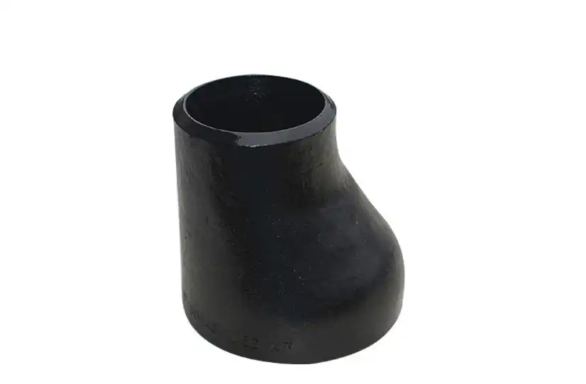
A reducer is used to change from one nominal pipe size to another in a plumbing system. The pipe is inserted into the socket part of the fitting in a socket-weld arrangement, and the junction is made by welding around the pipe at the entry to the fitting. The reducer consequently serves two tasks in the pipe arrangement: it provides the change in connection size necessary and it makes a permanent welded union.
This design is especially beneficial in small pipe systems when space is restricted and where threaded connections are unwanted. The fitting may be placed without the lengthy exterior engagement of a threaded joint, and the welded connection removes a threaded leak route. The actual geometry and dimensions nevertheless vary with the fitting design and relevant product standard. Engineers should not rely on a generic depiction but check the dimensional information from the manufacturer.
In small-bore systems valves, branches, instruments, supports, and other components are often packed together. In certain cases, a small socket-welded connection may assist with manufacturing and routing. This benefit is even more significant if the system undergoes several size changes and the available area for installation is limited.
Where These Reducers Commonly Appear?
Socket-weld fittings are most often used for process and utility pipelines when permanent welded connections are desired. Applications include chemical processing, oil and gas facilities, power generation, steam and utility services, and other industrial installations where tiny pipe diameters are paired with rigorous operating conditions.
The fit itself is not what determines if a system is appropriate for a certain service. For example, a reducer used for a chemical line must be compatible with the process fluid, operating temperature, pressure, corrosion environment, and the connecting pipe material. The same idea applies to servicing with steam or hydrocarbons. One fitting that works well for one application may need to be of a different material or pressure class for another.
This is a critical difference since “high pressure” or “high temperature” should never be a sufficient basis for the use of a socket weld reducer. The actual rating should be confirmed against the appropriate standard and fitting’s material and size. For example, ASME B16.11 gives the pressure classes of socket-weld end fittings, such as Class 3000, 6000, and 9000.
Why Socket Welding Can Be Attractive for Compact Pipework?
One practical benefit of socket welding is the comparatively simple fit-up of tiny pipe compared to various butt-weld arrangements. The socket offers a specified position to the pipe end, which may be useful for alignment during manufacture. This may be handy if a large number of tiny bore connections have to be constructed in a tight space.
A socket-welded junction may also create a lasting connection without the need of thread sealants. This makes it desirable for services where threaded joints can be an issue for leakage, vibration, or maintenance. At the same time, socket welds are not always the ideal solution for every service. Severe erosion, vibration, temperature cycling, and code requirements of the project may dictate that another joint design is more suited than crevice corrosion.
Therefore, the engineering choice should be based on the full plumbing service and not just on the kind of fitting.

Selecting a Socket Weld Reducer for the Actual Service
Start With Size, Schedule, and Connection Requirements
First stage in selection: validate the combination of sizes needed by the pipe design. The reducer should be of the same nominal size as the pipes to be joined, and the socket sizes should match. Other considerations include pipe schedule and wall thickness, since the connection geometry must be compatible with the pipe to be welded.
This is especially critical for small-bore systems where a tiny mismatch might impair fit-up and weld preparation. Therefore, the engineering team should use the piping isometric line list, pipe specification, or authorized fabrication drawings as the basis for choosing a fitting and not only the nominal diameter.
At this point the suitable pressure class and dimensional specification for the fitting should also be verified. ASME B16.11 is a major reference for forged socket-welding fittings. However, the applicable project specification may demand extra material certification, testing, labelling, or inspection.
Match the Material to the Pipe and Process Fluid
In many industrial plumbing applications, carbon steel is employed because it offers a reasonable balance between strength, availability, and cost. More appealing stainless steel is used when corrosion resistance, cleanliness, or particular process circumstances necessitate it. Depending on temperature, pressure, and chemical exposure, alloy steels or nickel-based alloys may be acceptable.
Do not pick materials only by the name of the fitting material. The reducer, pipe, weld filler metal, and surrounding components must be viewed as a system. For example, a stainless steel fitting may be OK for a corrosive process, but the whole joint still requires a proper welding operation and compatible filler material.
The engineers should also analyze the real process of deterioration, rather than merely picking a material that is labelled “corrosion resistant” for corrosive duty. Performance of components such as a socket weld reducer may be affected by chlorides, acids, moist conditions, temperature, pollution, and galvanic effects. In certain applications, the best answer could be 316 or 316L stainless steel, duplex stainless steel, or a nickel alloy. However, the ultimate decision should be a function of the process and materials engineering needs.
Check Pressure and Temperature Before Ordering
Consider the pressure and temperature together. The permissible pressure of a fitting may be different at different temperatures. A reducer that seems appropriate based on its nominal pressure rating may not satisfy the needed criteria at high temperature.
The design evaluation must thus include maximum operating pressure, design pressure, operating temperature, design temperature, probable pressure surges, and thermal cycling. If the line is exposed to frequent temperature fluctuations, the pipe system should also be evaluated for thermal expansion and the stresses that may arise.
This is when project specs and related pipe regulations really come into play. The pressure value in the catalogue description should not be part of the selection of a fitting. Engineering should check the applicable pressure-temperature rating and verify that it is compliant with the governing design code and associated pipe components.
Installation Practices That Protect the Welded Joint
Prepare the Pipe and Fitting Before Fit-Up
It starts far before you turn on the welding equipment. The ends of pipes and the surface of the socket should be clean and free from oil, grease, dirt, moisture, heavy oxidation, or other foreign matter that would interfere with the proper welding of the pipe.
The pipe should be cut square and prepared in line with the suitable specification for the welding technique. Remove burrs and damaged edges without altering the pipe geometry excessively. Then check the socket and pipe for damage, excessive clearance, or contamination.
It typically gets overlooked in tiny-bore operations because of the physically small components. In practice, contamination and poor fit-up might be obscured by modest dimensions. Dimensional inspections and clean preparation have a direct bearing on the quality of the completed joint.
Establish the Correct Fit-Up
The pipe should be placed into the socket to the appropriate depth and aligned according to the relevant piping code and welding technique. Where applicable to ASME B31.1, the assembly technique should require the pipe to be inserted to maximum depth and then withdrawn about 1/16 inch (roughly 1.5 mm in the 2024 language) from contact with the socket shoulder before welding.
That clearance should not be used as a uniform norm for all plumbing projects. Always examine the governing code, authorized WPS, fitting standard, and project specification before manufacture. The aim of the fit-up requirement is also not only “allowing thermal expansion." It is part of the regulation of the socket-weld joint configuration throughout manufacture and servicing.
Alignment is equally important. The reducer must be correctly aligned with the pipe it attaches to, and no undue force should be used to push a pipe that is not properly fitted into the socket. If considerable manipulation of the assembly is required prior to welding, the reason should be explored and not disguised by the weld.
Follow the Approved Welding Procedure
The welding technique must be chosen based on the material, thickness, service circumstances, design of the joint, and certified welding procedure. GTAW may be utilized if close control is necessary, although SMAW is popular in industrial manufacturing. The right option relies on the project, not on a general preference for one approach.
Welding parameters are to be taken from the authorized WPS. Preheat, interpass temperature, filler metal, current, voltage, travel speed, shielding gas, and cleaning needs may alter the completed junction. Additional controls may be required for the protection of the weld and nearby surfaces if the materials, e.g., stainless steels, are susceptible to oxidation.
Welders should also be qualified for the corresponding method and position. For example, ASME B31.1 has standards for certification of the WPS and welding workers involved in related power pipe operations, including work involving a socket weld reducer.
Fabrication workers should not use a general welding sequence for all reducers, but the permitted process for the individual material and service. This technique offers a considerably higher degree of technical control than merely advising welders to “use the correct heat input.”
Inspection and Quality Checks After Welding
Visual Inspection Comes First
A completed socket weld should be visually examined for obvious defects, irregular bead shape, undercut, cracking, excessive spatter, incomplete weld profile, or other conditions that could indicate poor workmanship. The surrounding fitting and pipe should also be checked for distortion or heat-related damage.
Visual inspection is valuable because it is fast and can identify problems before the piping moves to later fabrication or pressure testing stages. However, visual inspection does not prove that every internal or volumetric defect is absent.
Apply Nondestructive Testing When the Project Requires It
The appropriate NDT method depends on the piping class, service, governing code, project specification, material, and risk level. Depending on those requirements, inspection may involve methods such as liquid penetrant testing, magnetic particle testing, radiography, or ultrasonic examination.
It would be misleading to state that every socket weld requires radiography or ultrasonic testing. Conversely, it is equally inappropriate to suggest that visual inspection is always sufficient. The inspection plan should be established from the applicable code and project requirements.
The same principle applies to pressure testing. A piping system may require hydrostatic or pneumatic testing under its governing code, but the exact procedure and acceptance criteria depend on the design and service. Quality control should therefore be integrated into the piping project from procurement through fabrication and testing rather than added after welding is complete.
What Engineers and Buyers Should Confirm With the Supplier?
A reliable procurement process should establish the technical requirements before requesting a quotation. The supplier should receive the required pipe sizes, material grade, pressure class, applicable standard, service conditions, and any project-specific requirements.
For quality-sensitive projects, buyers may also need material certificates, dimensional inspection records, certificates of conformity, test reports, heat numbers, and traceability documentation. The exact documentation package depends on the project specification and applicable standards, but asking for it early avoids delays during inspection and final acceptance.
It is also useful to confirm how the manufacturer controls dimensions and marking during production. ASME B16.11 includes requirements related to dimensions, tolerances, materials, and marking, so these details should form part of the supplier evaluation rather than being treated as optional paperwork.
For an industrial buyer, supplier communication should be specific. Instead of asking only whether a manufacturer “has socket weld reducers,” it is more useful to provide the required size combination, material, pressure class, standard, quantity, and intended service. This gives the manufacturer enough information to verify whether the requested product matches the application.
Conclusion
Socket weld reducers can be a practical choice for small-bore piping systems where a compact welded connection is required between different pipe sizes. Their value comes from more than simply reducing pipe diameter. The fitting has to match the piping specification, pressure class, material system, dimensions, service conditions, and welding requirements before it can be considered suitable for the application.
For engineers and purchasing teams, the most reliable approach is to evaluate the fitting as part of the complete piping system. Confirm the applicable standard, verify material and pressure-temperature requirements, check dimensional compatibility, establish the correct fit-up, and follow the approved welding and inspection procedures. ASME B16.11 provides an important reference for forged socket-welding fittings, while the governing piping code and project specification determine how the joint should be designed, fabricated, and inspected.
When these factors are addressed before fabrication begins, a socket weld reducer becomes more than a simple size-transition fitting. It becomes a properly specified component within a controlled piping system, helping engineers achieve the connection geometry, material compatibility, and installation quality required for dependable small-bore service.
For more data or to talk about your particular attachment weld reducer or socket weld reducer needs, it would be ideal if you contacted us at oudi-04@oudiguandao.com.
FAQ
1. What is the maximum size for a socket weld reducer in small-bore piping?
Socket weld reducers are typically used in piping systems with diameters of 2 inches or less.
2. Can socket weld reducers be used in high-pressure applications?
Yes, socket weld reducers can be used in high-pressure applications when properly selected and installed.
3. How do I determine the correct material for a socket weld reducer?
Consider factors such as operating temperature, pressure, chemical compatibility, and industry standards.
4. Are socket weld reducers suitable for use with corrosive fluids?
Yes, when made from appropriate corrosion-resistant materials like stainless steel or special alloys.
References
1. Smith, J. (2019). Small-Bore Piping Systems: Design and Installation. Journal of Piping Engineering, 45(2), 78-92.
2. Johnson, R. (2020). Materials Selection for Socket Weld Fittings in Corrosive Environments. Corrosion Science and Technology, 55(3), 301-315.
3. Brown, A. (2018). Best Practices for Welding Socket Weld Reducers. Welding Journal, 97(4), 112-120.
4. Davis, M. (2021). Pressure Ratings and Temperature Considerations in Small-Bore Piping. International Journal of Pressure Vessels and Piping, 188, 104196.
5. Wilson, L. (2017). Quality Control Measures for Socket Weld Fittings in Industrial Applications. NDT & E International, 89, 34-42.
6. Thompson, K. (2022). Advancements in Socket Weld Reducer Design for High-Performance Piping Systems. Journal of Mechanical Engineering, 144(3), 031008.

Need help finding the right solution with our experts. Please contact us.
SINCE 1998 Your Reliable Pipeline Manufacturer