The Role of Steel Pipe Reducers in Flow Regulation and Pressure Management
In an industrial piping system, changing from one pipe diameter to another is more than a dimensional adjustment. The transition affects fluid velocity, local pressure loss, flow distribution, and the mechanical requirements of the surrounding piping. This is where steel pipe reducers become important. Designed to connect pipes of different sizes, reducers create a controlled geometric transition instead of forcing the flow through an abrupt change in diameter. Reducers are widely used in process piping, water treatment, chemical plants, power facilities, oil and gas systems, and other industrial applications. Their contribution to flow and pressure management is indirect but significant: the reducer geometry influences how velocity changes through the fitting and how much local pressure loss occurs. The right configuration can therefore support a more predictable piping layout, while an unsuitable configuration may introduce unnecessary turbulence, pressure loss, vibration, or operating difficulties. For engineers and purchasing teams, the key is not simply choosing a reducer that matches two pipe sizes. The configuration, material, wall thickness, connection method, applicable standard, operating temperature, and pressure conditions all need to match the requirements of the complete piping system.
Understanding How Steel Pipe Reducers Affect Flow Behaviour?
A reducer connects a larger pipe to a smaller one or a smaller pipe to a larger one when used in the opposite direction. Because the internal flow area changes, fluid velocity changes as well. For an incompressible fluid under steady conditions, the continuity relationship can be expressed as (Q = A \times V), meaning that a reduction in cross-sectional area generally corresponds to an increase in average velocity when the volumetric flow rate remains constant.
This does not mean that a reducer independently controls the system's flow rate. Valves, pumps, control devices, and other system components are normally responsible for active flow regulation. A reducer instead establishes the physical transition between pipe sizes and contributes to the hydraulic characteristics of that section of piping.
The shape of that transition matters. A gradual reduction can produce a different flow pattern and local loss than an abrupt contraction. For this reason, reducer geometry should be considered as part of the overall piping design rather than treated as a simple dimensional accessory.

Choosing Between Concentric and Eccentric Steel Pipe Reducers
When Concentric Reducers Are the Better Fit?
A concentric reducer has aligned centerlines, creating a symmetrical transition between the larger and smaller pipe diameters. This configuration is often suitable where maintaining a centered flow path is desirable, particularly in vertical piping arrangements and other installations where the orientation does not create an unwanted pocket for liquid or gas.
The symmetrical geometry also makes the fitting straightforward to integrate into many conventional piping layouts. In a vertical line, for example, the centerline arrangement can provide a practical transition without introducing an offset that complicates installation.
However, concentric construction should not automatically be considered the best option for every application. The orientation of the pipe, the process fluid, drainage requirements, pump arrangement, and available installation space can all influence the selection.
Why Eccentric Reducers Are Common in Horizontal Piping?
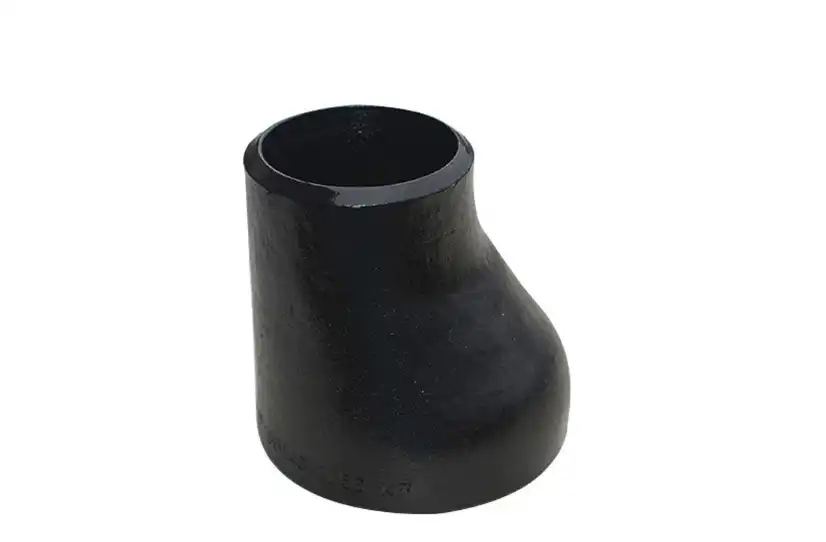
An eccentric reducer has its two pipe centerlines offset from one another. This creates a flat side on one portion of the fitting, and the orientation of that flat side becomes an important part of installation.
In horizontal piping, eccentric reducers can be selected when the design needs to control where liquid or gas can accumulate. The orientation may be chosen to support drainage or to reduce the possibility of an unwanted pocket, depending on whether the process is liquid service, gas service, slurry service, or connected to equipment such as a pump.
For example, the orientation used around a pump suction line can be different from the orientation preferred for a gravity-draining process line. The important point is that steel pipe reducers such as eccentric reducers should be specified together with their intended orientation rather than simply ordered as an “eccentric” fitting.
This is also why a good piping specification should describe the operating arrangement clearly. The reducer itself does not automatically prevent corrosion, blockage, or air accumulation; its effectiveness depends on how its geometry is positioned within the system.
How Reducer Geometry Influences Pressure Loss?
A reducer changes. Local Velocity and Pressure Conditions
When a fluid enters a smaller pipe section, its average velocity generally increases if the flow rate remains constant. The pressure distribution also changes as the fluid moves through the transition. Some of this pressure change is associated with the conversion between pressure and velocity, while some energy is permanently lost through friction and turbulence.
For engineers, the important distinction is between a useful pressure change associated with the system geometry and an undesirable permanent pressure loss. A reducer cannot simply be described as a device that “reduces pressure.” Its actual effect depends on the upstream and downstream conditions, reducer angle, pipe sizes, flow rate, fluid properties, and installation arrangement.
A well-designed transition can help avoid unnecessary losses compared with a poorly designed or abrupt change in diameter. However, every real fitting introduces some resistance to flow, so the reducer should be included in the hydraulic calculations used for the complete piping system.
Why Gradual Transitions Matter?
The geometry between the large and small ends influences how the flow contracts and develops downstream. If the transition is too abrupt for the application, the resulting flow separation and turbulence may increase local losses. A properly selected reducer provides a more controlled change in diameter and can therefore contribute to a predictable pressure-loss profile.
This becomes increasingly important in systems where pumps must maintain a specified operating point or where available pressure margin is limited. Even relatively small local losses can become relevant when many fittings, valves, bends, tees, and reducers are combined in a long piping network.
For that reason, engineers should evaluate the reducer as one component within the system's total pressure-loss calculation instead of judging performance from the fitting alone.
The Role of Steel Pipe Reducers in Flow Distribution
Complex piping networks often include multiple branches, equipment connections, and sections with different pipe diameters. Steel pipe reducers provide a practical way to connect these sections while keeping the overall piping layout compact and functional. By creating a gradual transition between different pipe sizes, they help engineers manage changes in flow conditions without requiring major changes to the surrounding pipe arrangement.
Their effect on flow distribution mainly comes from the change in internal geometry. When the pipe diameter decreases, fluid velocity generally increases, while a larger diameter reduces velocity under comparable flow conditions. These changes also influence pressure loss and hydraulic resistance within the connected section. During system design, engineers can consider the reducer's size, transition length, flow direction, and installation location when estimating pressure losses and determining how much flow should pass through different branches.
However, steel pipe reducers should not be treated as flow-control devices by themselves. Installing a reducer does not automatically balance flow between parallel branches. Differences in pipe length, valve settings, elevation, fittings, and equipment resistance can cause one branch to carry more flow than another, even when the branches use identical reducers. Engineers may therefore need balancing valves, control valves, or other dedicated components to achieve the desired distribution.
This distinction is important when designing industrial and commercial piping systems. Steel pipe reducers help create the required connection geometry and influence local flow conditions, but the final distribution depends on the design of the entire network. Treating reducers as passive components rather than active control devices allows engineers to make more accurate calculations, select suitable equipment, and avoid unnecessary pressure or flow problems during operation.
Where Steel Pipe Reducers Are Used in Industrial Piping?
Process and Chemical Piping
Chemical processing systems frequently contain equipment with different connection sizes. A reducer can provide the dimensional transition between process piping and equipment nozzles while allowing the piping layout to remain compact.
Material selection becomes especially important in these applications. The reducer must be compatible with the process fluid and the operating temperature and pressure. Depending on the service, carbon steel, stainless steel, alloy steel, or other materials may be considered.
The reducer should therefore be specified according to the actual process conditions rather than selected only by nominal pipe size.
Oil and Gas Piping
Oil and gas facilities contain extensive networks in which pipe diameter changes occur around processing equipment, gathering systems, manifolds, and transportation lines. In these applications, reducer selection may be influenced by pressure class, material requirements, welding conditions, corrosion considerations, and project specifications.
For high-pressure or critical service, the fitting's dimensional and material requirements need to be consistent with the applicable piping code and project documentation. ASME B16.9, for example, covers factory-made wrought buttwelding fittings and addresses requirements associated with dimensions, tolerances, materials, ratings, and marking.
This is one reason experienced buyers should provide a complete technical specification when requesting a quotation instead of asking for a reducer based only on “large size to small size.”
Water Treatment and Utility Systems
Water treatment plants, cooling-water systems, utility lines, and general industrial piping also use reducers to connect different pipe sizes. Compared with some process applications, the fluid conditions may be less severe, but hydraulic performance and installation orientation can still matter.
In systems where drainage, air removal, or maintenance access is important, the choice between concentric and eccentric construction should be made according to the actual piping arrangement.
What Should Engineers Check Before Ordering a Steel Pipe Reducer?
The most reliable approach is to treat steel pipe reducers selection as a specification exercise rather than a simple product-size decision. The first requirement is the nominal size of both ends, followed by the reducer type and end connection. For butt-welded applications, the dimensions and welding-end preparation need to correspond with the applicable standard and mating pipe.
Material is another major consideration. Carbon steel may be appropriate for many general industrial services, while stainless steel or alloy steel may be required where corrosion resistance, temperature, strength, or process compatibility demands it. The material grade should be confirmed against the project specification rather than assumed from the general term “steel reducer.”
Operating pressure and temperature should also be considered together. A fitting's suitability cannot be determined from nominal size alone because pressure-temperature conditions affect material selection and allowable service conditions.
Wall thickness deserves equal attention. The reducer should be compatible with the connected pipe and the design requirements of the piping system. Dimensional tolerances, welding-end preparation, inspection requirements, marking, and documentation may also be specified for industrial projects.
For critical applications, buyers may additionally request material certificates, dimensional inspection records, non-destructive examination requirements, hydrostatic or other testing documentation where applicable, and traceability information. These documents provide a more useful basis for quality verification than a general statement that a product is “high strength” or “high quality.”
How Proper Reducer Selection Supports Reliable Piping Design?
The value of a reducer is ultimately determined by how well it fits the system around it. A technically suitable fitting should connect the required pipe sizes while remaining compatible with the fluid, pressure, temperature, installation orientation, welding method, and applicable standards.
Good selection also reduces the chance of creating avoidable installation problems. A reducer with the wrong orientation can interfere with drainage or gas removal. An unsuitable material can create compatibility concerns. Incorrect wall thickness or dimensions can complicate welding and inspection. A fitting that does not match the project's standard may also create documentation or acceptance problems during procurement.
This is why the best reducer specification starts with the piping system rather than the fitting catalog. Engineers should first establish the operating conditions and connection requirements, then select the reducer configuration and material that meet those conditions.
For manufacturers and suppliers, this also creates an opportunity to provide more useful technical support. Instead of supplying a reducer based only on two nominal diameters, a qualified supplier can review the required material, dimensions, standard, end preparation, quantity, and application conditions before production.
Conclusion
Steel pipe reducers play an important supporting role in flow regulation and pressure management, but their function is best understood in terms of geometry and hydraulic behavior rather than active pressure control. By providing a controlled transition between different pipe diameters, they influence fluid velocity, local pressure loss, and the flow conditions within connected sections of an industrial piping system.
Concentric and eccentric designs serve different installation requirements, while material, wall thickness, dimensions, end connections, and applicable standards determine whether a particular reducer is suitable for a given service. ASME B16.9 is one relevant standard for factory-made wrought buttwelding fittings, while the final requirements depend on the piping code and project specification applicable to the installation.
For procurement teams, the most important lesson is that a reducer should not be selected by size alone. A complete specification that considers operating conditions, fluid characteristics, orientation, material, dimensions, and quality requirements provides a much stronger basis for reliable installation. When these factors are evaluated together, steel pipe reducers can provide a practical and predictable transition between different sections of industrial piping while supporting the overall hydraulic and mechanical requirements of the system.
For more information about our high-quality steel pipe reducers and other piping components, please contact us at oudi-04@oudiguandao.com. Since 1998, Cangzhou Oudi Pipe Manufacture Co., Ltd. has been a frontrunner among Chinese producers of carbon steel pipe fittings, valves, and flanges, catering to more than 300 clients in 40 distinctive nations.
References
1. Smith, J. A., & Johnson, R. B. (2019). Advanced Flow Control Techniques Using Steel Pipe Reducers. Journal of Industrial Fluid Dynamics, 45(3), 278-295.
2. Chen, L., et al. (2020). Computational Fluid Dynamics Analysis of Pressure Drop in Steel Pipe Reducers. International Journal of Pressure Vessels and Piping, 182, 104093.
3. Thompson, E. M. (2018). Optimizing Piping System Design: The Role of Steel Pipe Reducers. Chemical Engineering Progress, 114(8), 38-45.
4. Patel, S., & Gonzalez, M. (2021). Experimental Study on Flow Characteristics of Eccentric Steel Pipe Reducers. Experimental Thermal and Fluid Science, 122, 110281.
5. Wilson, D. R. (2017). Pressure Management Strategies in Industrial Piping Systems: A Comprehensive Review. Applied Energy, 201, 174-188.
6. Yamamoto, K., et al. (2022). Innovative Applications of Custom-Designed Steel Pipe Reducers in High-Pressure Oil and Gas Pipelines. Journal of Petroleum Science and Engineering, 208, 109662.

Need help finding the right solution with our experts. Please contact us.
SINCE 1998 Your Reliable Pipeline Manufacturer