Top Installation Techniques for Carbon Steel Elbows
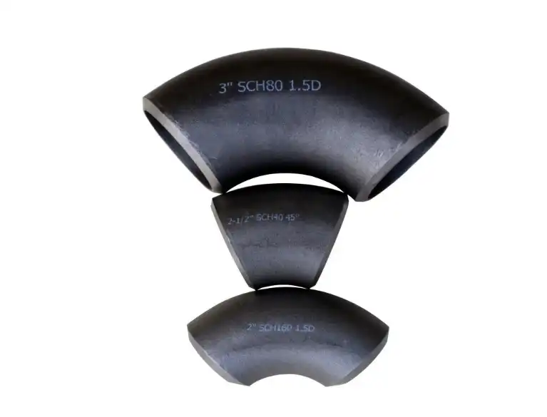
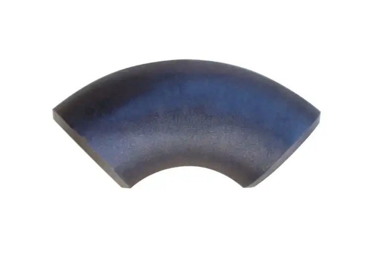
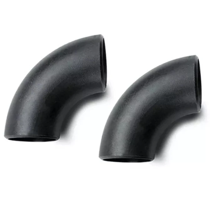
Carbon steel elbows are widely used in piping systems where the line needs to change direction without introducing an unnecessarily complicated layout. But their performance is not just a matter of choosing the right elbow and welding it in. The fitting must be compatible with the pipe in material, size, wall thickness, and connection type, and the installation must control for alignment, welding quality, and thermal stress. A little misalignment at the elbow might become more of an issue when the pipe system is pressurized or subjected to frequent temperature variations. For engineers, fabricators, and installation crews, a successful installation begins before the welding machine is turned on. Check the elbow, prepare the pipe ends, and compare the planned orientation to the piping designs. Welding should next be carried out in accordance with the authorized process for the materials and service circumstances. The installation procedures that follow describe where difficulties are often encountered and how a more regulated approach may enhance the dependability of carbon steel pipe systems.
Prepare the Elbow and Piping Before Assembly
Inspect Material, Dimensions, and End Conditions
The first step is to make sure that the elbow that has been delivered to the job site is, in fact, appropriate for the piping system. Confirm material grade with project specifications. Confirm nominal size, wall thickness, elbow angle, and end arrangement. Confirmation is particularly important for butt-weld fittings, including the bevel shape and end condition since they directly impact joint preparation and welding.
“Visual inspection should also be carried out before installation. Look for cracks, dents, severe corrosion, broken bevels, or other issues that will impede fit-up. If the fitting has been kept outside or has been exposed to moisture, the surface should be cleaned and inspected prior to entering the manufacturing process. Dirt, oil, loose scale, paint, and moisture near the weld region may adversely affect welding. Such contaminants are liable to cause problems.
Dimensional verification is particularly critical when elbows are being placed into pre-fabricated pipe sections. Where the two components are nominally the same size, the actual size or final preparation may vary, producing an undesirable offset. It is much simpler to check dimensions before assembling the joint than to repair the mistake after the junction is welded.
Prepare Clean and Consistent Joint Surfaces
The ends of the pipe and elbow should have a clean, stable weld surface. Remove rust, oil, moisture, paint, and other impurities from the defined region of the welding operation. Mechanical cleaning may be helpful to remove scale or surface corrosion. Care should be taken to prevent excessive grinding, which might change the bevel geometry or diminish the wall thickness.
Also need to verify the condition of the pipe ends. A pipe that is out of round, broken, or cut improperly may not sit properly on the elbow. In certain circumstances, application of force to the components alone might lead to residual stress in the joint. Before the elbow is set, proper cutting, beveling, and preparation should be done.
For projects with specific welding requirements, the joint preparation should be in accordance with the appropriate design and authorized welding method, not a generic bevel angle or root gap. This is one of the cases when the project requirements and competent welding processes must be followed rather than generic suggestions on installation.
Confirm Material Compatibility and Service Conditions
The material compatibility must be determined before the manufacturing starts. The elbow and the connecting pipe should be appropriate for the same service conditions, but this does not imply that they have to be identical components. The material grades, mechanical qualities, welding requirements, and filler materials should be considered together.
The operational environment matters too. The selection and installation of carbon steel pipe components are influenced by temperature, pressure, fluid properties, corrosion exposure, and cyclic service. For example, an elbow in a high-temperature process line may have different welding and inspection requirements than an elbow in a low-pressure utility system.
The protective measures for carbon steel elbows should be determined as part of the overall piping design where the piping system is exposed to a corrosive atmosphere or aggressive internal medium. Do not add coatings, corrosion allowances, insulation details, or other protective techniques indiscriminately while installing. They should meet the project requirements and the service environment.
Choose the Welding Process According to the Installation
SMAW for Flexible Field Welding
Shielded Metal Arc Welding (SMAW), commonly called stick welding, remains a practical option for many carbon steel piping installations, particularly in field conditions. The process uses a flux-coated consumable electrode to create an arc between the electrode and the workpiece. As the electrode melts, it supplies filler metal while the coating provides shielding and forms slag over the weld.
SMAW can be useful where access to the joint is limited or where the worksite does not provide ideal conditions for continuous shielding gas coverage. However, electrode selection, storage, preheating where required, interpass temperature, current, and welding position should follow the applicable qualified procedure.
The elbow should first be positioned and held securely before tack welding. Tack welds help maintain the intended orientation during subsequent passes, but they do not eliminate the need to monitor alignment as welding progresses. Heat input can cause the joint to move, particularly when the fitting is connected to relatively long or rigid pipe sections.
SMAW also requires attention to electrode condition. Moisture exposure can affect certain low-hydrogen electrodes, so storage and handling should follow the manufacturer's requirements and the applicable welding procedure. These details are often overlooked during field installation but can have a direct effect on weld quality.
GTAW for Controlled and Precise Welds
Gas Tungsten Arc Welding (GTAW), also known as TIG welding, provides precise control over the welding arc and heat input. Unlike SMAW, the tungsten electrode is non-consumable, while filler metal can be added separately when required. An inert shielding gas protects the weld area from atmospheric contamination.
GTAW can be particularly useful for root passes or applications where precise control of the weld pool is important. Argon is commonly used as the shielding gas, although the exact gas selection should follow the qualified welding procedure and the equipment manufacturer's requirements.
Cleanliness is especially important when using GTAW. Contamination on the joint surface, filler rod, tungsten electrode, or surrounding area can affect weld quality. The welding operator also needs to maintain suitable torch positioning and shielding throughout the operation.
Although GTAW generally has a lower deposition rate than processes designed for higher production speeds, its control can make it valuable for critical or precision applications. It should therefore be selected because its process characteristics suit the joint, rather than simply because it is considered a higher-quality welding method.
GMAW for Efficient Shop and Fabrication Work
Gas Metal Arc Welding (GMAW), commonly referred to as MIG or MAG welding depending on the shielding arrangement, uses a continuously fed wire electrode and shielding gas. It can offer higher productivity than manual stick welding and is often suitable for controlled fabrication environments.
For carbon steel elbows, the wire electrode, shielding gas, welding current, voltage, travel speed, and other parameters should be selected according to the material and qualified procedure. The joint still needs to be correctly aligned and tack welded before the final weld is deposited.
One important limitation of GMAW in outdoor work is sensitivity to wind. Strong airflow can disturb shielding gas and expose the molten weld pool to atmospheric contamination. Adequate wind protection and suitable site controls are therefore necessary when the process is used outside a controlled workshop.
The decision between SMAW, GTAW, and GMAW should ultimately be based on the project requirements rather than assuming that one process is universally better. A combination of processes may also be appropriate, such as using GTAW for the root and another qualified process for subsequent passes.
Control Alignment Before and During Welding
Establish the Correct Centerline and Orientation
A carbon steel elbow must be correctly oriented before the joint is permanently welded. The fitting should follow the piping isometric, layout drawing, or fabrication drawing so that the change in direction occurs at the intended location.
Pipe alignment clamps, external lineup clamps, fixtures, and other suitable tools can help maintain the position during fit-up. The objective is not simply to make the outside surfaces look aligned. The pipe centerline, elbow angle, and connection position all need to correspond with the intended piping geometry.
For larger-diameter piping or complicated assemblies, additional measurement methods may be justified. Laser alignment equipment can be useful where several connected sections need to maintain a common reference line. In smaller installations, properly selected levels, squares, tapes, and other calibrated tools may be sufficient.
Forcing an elbow into position with excessive mechanical pressure should be avoided. If substantial force is required to bring the pipe and fitting together, the underlying layout or dimensional problem should be investigated before welding continues.
Verify Elbow Angles and Fit-Up
Elbow angle is one of the most visible characteristics of the fitting, but installation accuracy involves more than checking whether the elbow is nominally 45° or 90°. The fitting must also be positioned correctly relative to the connected pipe sections and adjacent equipment.
A level, angle gauge, digital inclinometer, or other suitable measuring instrument can be used according to the accuracy required by the project. For prefabricated systems, measurements should be compared with the approved drawings rather than relying only on visual judgment.
Fit-up should also be checked after tack welding because the components may move slightly during this stage. The final inspection should confirm that the joint has not developed excessive angular misalignment, offset, or unwanted rotation.
This becomes particularly important when several elbows are installed close together. A small orientation error at the first fitting can shift the position of downstream components and eventually make equipment connections difficult to complete. Checking each section as fabrication progresses is therefore more effective than waiting until the entire piping run has been assembled.
Account for Welding Distortion
Welding introduces localized heat, and uneven heating and cooling can cause distortion. The risk becomes more noticeable when the piping arrangement is rigid or when multiple joints are welded in a confined area.
The welding procedure should define the appropriate sequence and control of heat input. Balanced welding sequences can help limit unnecessary movement, while suitable temporary supports and fixtures can maintain the intended geometry during fabrication. Tack welds also need to be properly distributed and made in accordance with the welding procedure.
Correcting distortion by applying excessive force after welding is not a substitute for controlling it during fabrication. If the finished assembly does not align with the drawing, the cause should be evaluated before corrective work is attempted.
For critical piping systems, dimensional inspection after welding can provide useful evidence that the finished assembly remains within the specified tolerances. The extent of inspection should be determined by the project requirements and applicable code.
Consider Thermal Movement in the Completed Piping System
Allow for Expansion During Design and Installation
Carbon steel expands and contracts as its temperature changes. Carbon steel elbows installed in a piping system therefore do not operate in exactly the same dimensional condition at ambient temperature and at operating temperature.
Thermal movement should be addressed at the piping-system design stage. Long straight runs, elevated operating temperatures, fixed equipment connections, and rigid supports can all contribute to thermal stress. Elbows often form part of the natural flexibility of a piping system, but their ability to accommodate movement depends on the complete arrangement of pipe, bends, supports, anchors, and connected equipment.
For this reason, installers should work from the approved piping layout rather than adding expansion devices or changing support locations without engineering review. Where a piping flexibility analysis has been specified, the installation should preserve the geometry used in that analysis.
Avoid Locking the Piping Into an Unintended Position
An elbow can be correctly aligned at ambient temperature but still become highly stressed if the piping system is unintentionally restrained. Supports and guides should therefore be installed according to the design rather than simply positioned wherever they are convenient during construction.
Special attention is warranted around pumps, compressors, heat exchangers, and other equipment with defined nozzle loads. An installation that appears visually acceptable may still transfer excessive forces to connected equipment if thermal movement and support conditions have not been properly considered.
Post-weld heat treatment should also be treated as a code- and procedure-dependent requirement rather than a universal installation step. Where the applicable material specification, piping code, or qualified welding procedure requires PWHT, the process should be completed and documented accordingly.
Inspect the Finished Elbow Installation Before Service
Examine welds and dimensional condition
After welding is complete, the installation should be inspected according to the project's quality plan. Visual inspection can identify obvious problems such as undercut, excessive reinforcement, surface cracking, incomplete-looking weld profiles, or visible damage around the fitting.
Depending on the service and applicable code, additional non-destructive examination may be required. Radiographic testing, ultrasonic testing, magnetic particle testing, or other methods may be selected according to the joint type, material, service conditions, and inspection requirements.
Dimensional checks should not be forgotten at this stage. Confirm that the elbow remains correctly oriented and that the completed piping section matches the approved layout. This is particularly valuable before insulation, painting, or other finishing work makes the joints more difficult to access.
Complete Documentation and Pressure Testing
Quality documentation provides important evidence that the installation was completed under controlled conditions. Depending on the project, records may include material certificates, welding procedure qualifications, welder qualifications, inspection reports, non-destructive examination results, and pressure-test documentation.
The completed piping system should be tested according to the applicable design code and project specification before being placed into service. The test method, pressure, duration, and acceptance criteria should be established by the responsible engineering and quality teams rather than copied from a generic installation guide.
For procurement teams, this also highlights why selecting the elbow only by nominal diameter and angle is rarely sufficient. Before ordering, it is useful to confirm the required material grade, standard, dimensions, wall thickness, end preparation, quantity, inspection requirements, and documentation package with the supplier. Clear information at the purchasing stage reduces the chance of receiving components that require modification before fabrication.
Conclusion
Mastering the top installation techniques for carbon steel elbows is essential for creating robust and efficient piping systems. Proper installation begins with verifying the fitting and pipe materials, dimensions, end preparation, and service conditions before assembly. From there, the welding process should be selected according to the joint, production environment, and qualified welding procedure, while alignment and heat control should be maintained throughout fabrication.
A reliable elbow installation also requires attention to the piping system as a whole. Thermal movement, support conditions, equipment connections, weld inspection, and pressure testing can all influence the long-term performance of the completed line. For procurement and engineering teams, providing the supplier with complete technical requirements before production is equally important because the correct material, dimensions, standards, and documentation help prevent avoidable fabrication delays.
When carbon steel elbows are selected carefully and installed under controlled procedures, they can provide a dependable solution for directional changes across a wide range of industrial piping applications. Working with a supplier that can support dimensional requirements, material documentation, inspection needs, and project-specific specifications can further simplify the transition from procurement to final installation.
For further information or assistance with carbon steel elbow installations, please don't hesitate to contact us at oudi-04@oudiguandao.com. Our team of experts is ready to help you achieve optimal results in your piping projects.
References
1. Smith, J. (2020). Advanced Welding Techniques for Carbon Steel Piping Systems. Journal of Welding Technology, 15(3), 78-92.
2. Johnson, R., & Thompson, A. (2019). Best Practices in Piping System Design and Installation. Industrial Engineering Quarterly, 42(2), 112-128.
3. Brown, M. (2021). Thermal Expansion Considerations in High-Temperature Piping Systems. ASME Journal of Pressure Vessel Technology, 143(4), 041302.
4. Davis, L., & Wilson, K. (2018). Quality Control Measures for Carbon Steel Elbow Installations. International Journal of Pipeline Engineering, 9(1), 23-37.
5. Roberts, S. (2022). Advancements in Alignment Technologies for Precision Piping Installations. Mechanical Engineering Today, 28(4), 55-69.
6. Anderson, P., & Lee, C. (2020). Corrosion Prevention Strategies for Carbon Steel Piping Components. Materials Performance, 59(6), 30-45.

Need help finding the right solution with our experts. Please contact us.
SINCE 1998 Your Reliable Pipeline Manufacturer