Where to Use Concentric Reducers in Water and Oil Pipeline Systems
A pipeline rarely maintains the same diameter from the source to the final point of use. Pumps, valves, tanks, processing equipment, storage facilities, and distribution branches often require different pipe sizes, making reducers an essential part of many piping layouts. Among the available options, concentric reducers are commonly used when the connected pipes share the same centerline and a symmetrical transition between diameters is suitable for the system. They link a huge pipe to a tiny pipe, not just their worth. The choice of a concentric design or not depends on the placement of the reducer, the properties of the fluid to be conveyed, the working pressure, the flow velocity, and the surrounding equipment. Therefore, in water and oil pipeline systems, the determination of the reducer should be considered as a part of the entire design of the piping and not as a single fitting decision. A well-designed reducer may provide a predictable transition between pipe diameters and can lead to a simpler architecture for integration with pumps, valves, vessels, and other components. But don’t assume that a concentric reducer is appropriate for every segment of every pipeline. Knowing where it works well, where another configuration would be better, and what engineers need to check before installing might result in a more reliable system.
Where Are Concentric Reducers Commonly Used in Water Pipeline Systems?
Water systems include multiple locations where a larger distribution pipe must link to smaller process lines, equipment nozzles, valves, or branches. Where the piping configuration permits the two pipe centerlines to stay aligned, a concentric reducer is a simple transition. This makes it suitable for a variety of industrial and municipal water applications, especially if the equipment around the perimeter is similarly structured around a common centerline.
Connections Between Different Water Pipe Sizes
One of the simplest uses is the connecting of pipes with differing nominal sizes. A water pipeline may have quite a big flow through the main header and then reduce to a smaller line feeding a specific piece of equipment or process segment. A concentric reducer allows a progressive change in geometry between various sizes, instead of a sudden shift in pipe size.
This arrangement may be advantageous if the pipe arrangement is symmetrical and there is no particular necessity to keep the bottom or top surface level. The reducer is yet to be chosen based on real pipe size, wall thickness, pressure requirements, material, and appropriate project standards. Matching the sizes of the inlet and outlet does not always make the fitting suitable for the service.
Water Treatment and Industrial Process Piping
Water treatment plants are generally designed with a range of pipe diameters as water flows around the plant between pumps, filters, tanks, heat exchangers, dosing systems, and other process equipment. In such circumstances, it is possible to install concentric reducers when it is required to center the connection and the surrounding equipment design allows for it.
For instance, a bigger process line would have to adapt to the nozzle of a smaller vessel or treatment equipment. A circular reducer may help make this transition compact and straightforward to assemble into the pipe. In the final design, one should consider the direction of flow, specifications of equipment manufacturers, available space for installation, and the likelihood of air collection in that particular length of pipe.
Pump and Equipment Connections
Concentric reducers may also be used around pumps and other equipment where the pipe configuration needs a centered reduction. But the connection should not be chosen just because the fitting is tiny. Suction and discharge pipework for pumps have separate design requirements, and the reducer layout might influence the flow conditions entering the machine.
For pumps, engineers are especially concerned with preventing situations that might cause air or vapor buildup and with providing enough flow to the pump in suction applications. An eccentric reducer could be better for various suction configurations, depending on the angle and layout. This is why the reducer should be examined along with the pump nozzle, the pipe orientation and support arrangement, and the operating circumstances and not in isolation.
Where Do Concentric Reducers Fit in Oil Pipeline Systems?
Oil pipelines also contain frequent changes in diameter, particularly around pumping stations, processing equipment, storage facilities, and connections between different sections of a transportation network. The suitability of a concentric reducer depends on the type of oil, temperature, viscosity, pressure, velocity, and piping configuration. For that reason, the same fitting arrangement should not automatically be applied to every section of an oil pipeline.
Crude Oil Transfer and Gathering Lines
In crude oil systems, different pipe sizes may be required as fluids move from gathering systems toward larger transportation lines or processing facilities. Concentric reducers can be used where the centerline of the connected pipes should remain aligned and where the resulting geometry is compatible with the operating conditions.
The reducer provides a controlled transition between the upstream and downstream pipe diameters. Its purpose is not to eliminate pressure loss completely, because every change in flow area introduces some local loss. Instead, the goal is to use a properly designed fitting so that the change in cross-sectional area is predictable and consistent with the hydraulic design of the system.
This distinction is important for oil transportation. A reducer should not be described as a component that automatically “reduces pressure drop.” The actual pressure loss depends on the reducer geometry, diameter ratio, flow rate, fluid properties, surface condition, and other components in the line. Engineers normally evaluate the fitting as part of the complete hydraulic system.
Connections Around Oil Processing Equipment
Refineries and oil processing plants use extensive networks of pipes connecting separators, heat exchangers, vessels, pumps, valves, storage tanks, and other equipment. These systems frequently require transitions between different pipe diameters, and concentric reducers can be useful where the equipment connections are aligned along a common centerline.
In these locations, the fitting must be compatible with the process fluid and operating environment. Material selection becomes particularly important when the system handles corrosive fluids, elevated temperatures, or high-pressure hydrocarbons. Depending on the service, engineers may need to consider carbon steel, stainless steel, alloy steel, or other specified materials, along with the applicable material and fabrication requirements.
A reducer that has the correct dimensions but the wrong material or pressure rating is not an appropriate engineering choice. Procurement teams should therefore confirm the complete specification rather than ordering solely according to the nominal pipe sizes.
Pump Discharge and Transfer Sections
Oil transfer systems frequently use pumps to move fluids between storage tanks, process units, and transportation lines. On pump discharge piping, a concentric reducer may be suitable when a centered transition is required and the hydraulic arrangement supports it.
The reduction ratio should be considered together with the expected flow rate and velocity. A significant change in diameter can alter velocity and local pressure losses, so the reducer should form part of the hydraulic calculation. This approach is more reliable than assuming that a smaller outlet will automatically improve pumping efficiency.
When Is a Concentric Reducer a Good Choice for Pipeline Design?
The most important factor is not whether the system carries water or oil, but whether the physical arrangement and operating conditions are compatible with a concentric transition. Several characteristics can make this configuration particularly practical.
When the Pipe Centerlines Need to Remain Aligned?
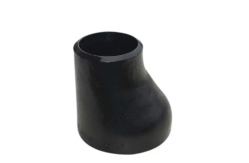
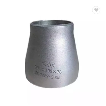
The defining feature of a concentric reducer is that the larger and smaller openings share the same centerline. This makes the fitting suitable for piping layouts where symmetrical reduction is preferred and there is no need to deliberately offset the pipe toward one side.
This can simplify connections to centered equipment nozzles and create a visually straightforward piping arrangement. It can also make the reducer easier to integrate into compact layouts where the surrounding components have already been positioned around a common axis.
When a Symmetrical Transition Is Preferred?
A symmetrical transition can be useful in systems where the pipe geometry needs to remain centered throughout the reduction. The fitting provides a continuous change in diameter rather than an abrupt step, which allows the designer to account for the resulting hydraulic behavior as part of the overall system calculation.
However, concentric reducers with a symmetrical transition are not automatically the best solution. In horizontal liquid lines, for example, engineers may need to consider whether an eccentric configuration would better control air or vapor accumulation. The choice should therefore follow the process requirements rather than a general preference for one reducer type.
When Space and Equipment Arrangement Support the Design?
Concentric reducers can be practical when the available space and equipment layout favor an inline, centered connection. Their simple geometry can make them convenient for pipe assemblies connecting equipment with different nozzle sizes.
Even so, “space saving” should not be treated as a universal advantage. The total installation space also depends on the reducer length, adjacent fittings, valves, flanges, pipe supports, insulation, and maintenance access. A good layout considers all of these factors before deciding that a concentric reducer provides the most practical arrangement.
What Should Engineers Check Before Selecting Concentric Reducers?
Correct selection requires more than identifying the inlet and outlet diameters. A reducer is part of a pressure-containing piping system, so its specification should be consistent with the complete service condition.
Pipe Size, Wall Thickness, and Pressure Rating
The first step is to confirm the nominal sizes and wall thicknesses of the connected pipes. The reducer must be compatible with these dimensions and with the pressure rating required by the system. Operating pressure and temperature should be considered together because material strength and allowable pressure can change with temperature.
The engineer should also verify the applicable fitting standard and project specification. Depending on the application, requirements may cover dimensions, material, manufacturing, inspection, testing, marking, and documentation. These details are particularly important for oil and industrial water systems where traceability and quality documentation may be part of the procurement requirement.
Material Compatibility With the Fluid
Water and oil are broad service categories rather than single operating conditions. Clean water, treated water, seawater, process water, crude oil, refined products, and chemically treated fluids can impose very different demands on the fitting.
Material selection should therefore consider corrosion exposure, operating temperature, fluid composition, and compatibility with the connected piping. When the reducer and adjacent pipe have significantly different material characteristics, engineers may also need to evaluate welding procedures and potential differences in thermal expansion or corrosion behavior.
Flow Rate and Diameter Reduction
Flow rate is another essential consideration because reducing the pipe diameter changes the flow velocity. If the same volumetric flow passes through a smaller cross-sectional area, the average velocity increases. This change can influence pressure loss, noise, erosion potential, and the operating conditions of downstream equipment.
For this reason, the diameter ratio of concentric reducers should be evaluated as part of the hydraulic design. The objective is not simply to make the pipe smaller, but to achieve the required downstream flow conditions without creating unnecessary operating problems.
How Should Concentric Reducers Be Installed in Water and Oil Pipelines?
Installation should follow the approved piping design and the manufacturer's requirements. The reducer needs to be correctly aligned with the connected pipes, and the joints should be prepared according to the specified connection method. For welded systems, this includes appropriate fit-up, welding procedures, inspection, and any required post-weld treatment.
Orientation deserves particular attention, but it should not be described using rules intended for eccentric reducers. Because a concentric reducer is symmetrical around its centerline, it does not have the same flat-side orientation issue as an eccentric reducer. Instead, engineers should evaluate the entire pipe arrangement for potential air or vapor pockets, drainage requirements, equipment connection requirements, and access for inspection.
This distinction becomes especially relevant in water systems. Air accumulation is normally controlled through the overall pipeline profile, vents, air-release valves, and appropriate system design rather than simply by turning a concentric reducer in a particular direction. In oil systems, vapor behavior, temperature, fluid volatility, and operating pressure may require additional process-specific considerations.
After installation, the completed pipeline should undergo the pressure or leak testing required by the applicable project specification and code. Testing should cover the reducer and its connections as part of the complete pressure boundary rather than treating the fitting as an isolated component.
When Might Another Reducer Configuration Be More Appropriate?
A strong engineering article should also explain when not to use the featured product. Concentric reducers are not a universal replacement for eccentric reducers.
In some horizontal liquid piping arrangements, an eccentric reducer may be selected to help manage the position of the pipe's upper or lower surface. This can be particularly relevant near pump suction piping or in systems where preventing air or vapor accumulation is an important design objective. The correct orientation then depends on the specific service and piping configuration.
Similarly, a concentric reducer may not be appropriate simply because the connected pipe sizes are different. If the equipment manufacturer specifies a particular transition geometry, or if the process design requires a different configuration, those requirements take priority.
The practical rule is straightforward: choose the reducer based on the behavior and geometry of the complete piping system, not only on the diameter difference between two pipes.
Conclusion
The right place to use concentric reducers is determined by the relationship between pipe geometry, fluid service, equipment arrangement, and operating conditions. In water systems, they can be practical for centered transitions between different pipe sizes, connections to treatment equipment, and selected pump or process piping arrangements. In oil systems, they can serve similar functions around transfer lines, processing equipment, storage facilities, and pump discharge sections when the symmetrical centerline configuration meets the design requirements.
Their use should not be based on the assumption that concentric reducers automatically eliminate pressure loss, maintain laminar flow, or provide the best solution in every high-pressure application. The actual performance of a reducer depends on the diameter ratio, flow rate, fluid properties, pressure, temperature, installation arrangement, and the design of the surrounding pipeline. Engineers should also distinguish clearly between concentric and eccentric reducers, especially when dealing with horizontal liquid lines and pump suction arrangements.
Before purchasing or installing a concentric reducer, the project team should confirm pipe dimensions, material compatibility, pressure and temperature requirements, applicable standards, connection method, and installation conditions. When these factors are considered together, the reducer becomes more than a simple connection between two pipe sizes; it becomes a properly specified component of a reliable water or oil transportation system.
For more information about our high-quality concentric reducers and other pipeline components, please contact us at oudi-04@oudiguandao.com. Since 1998, Cangzhou Oudi Pipe Manufacture Co., Ltd., a Chinese industry powerhouse, has been satisfying clients in more than 40 nations with its carbon steel pipe fittings, valves, and flanges.
References
1. Smith, J. A. (2019). Optimizing Flow Dynamics in Industrial Pipelines: The Role of Concentric Reducers. Journal of Fluid Engineering, 45(3), 278-292.
2. Johnson, R. B., & Williams, K. L. (2020). Pressure Management Techniques in Oil and Gas Transportation Systems. International Journal of Pipeline Technology, 12(2), 156-170.
3. Chen, Y., & Zhang, X. (2018). Enhancing Efficiency in Water Distribution Networks: A Comprehensive Guide to Pipe Fittings. Water Resources Management, 33(4), 412-428.
4. Thompson, M. S. (2021). Materials Selection for High-Pressure Pipeline Components in Corrosive Environments. Corrosion Science and Technology, 56(1), 89-105.
5. Garcia, A. L., & Rodriguez, C. M. (2017). Installation Best Practices for Concentric Reducers in Industrial Fluid Systems. Industrial Engineering and Management, 22(3), 201-215.
6. Lee, H. K., & Park, S. J. (2022). Maintenance Strategies for Long-Term Reliability of Water and Oil Pipeline Infrastructure. Journal of Infrastructure Maintenance and Resilience, 8(2), 145-160.

Need help finding the right solution with our experts. Please contact us.

SINCE 1998 Your Reliable Pipeline Manufacturer