Common Reducer Fitting Dimensions and How to Read Them
Anyone involved in piping design, fabrication, installation, or procurement will eventually need to work with reducer fitting dimensions. A reducer is used to join pipes of various nominal diameters to provide a smooth transition from the bigger to the smaller aperture. The component may be basic, but dimensions might impact fit-up, welding, routing, flow behavior, and space available in the pipe system. To read a reducer properly requires looking beyond the two end sizes. The following information may be useful, if appropriate: NPS or DN; overall length; outer diameter; wall thickness or schedule; end preparation; material grade; and applicable manufacturing standard. ASME B16.9 is one of the major standards for wrought factory-made fittings for butt-welding reducers. The present ASME B16.9-2024 provides overall dimensions, tolerances, ratings, tests, and labeling for factory-made wrought buttwelding fittings NPS 1/2 to NPS 48. Finding a reducer with the proper nominal sizes is not the aim for engineers and purchasers. The dimensions should be consistent with the linked pipe, appropriate standard, service circumstances, and installation layout. Once you understand the links between them, a dimensional design or product data sheet is much simpler to decipher.
Understanding the Two Main Reducer Configurations
The reductions are commonly classified into concentric and eccentric types. Both link various pipe diameters, but the relationship of their centerlines is different, and that distinction might matter big time when doing piping layout.
Concentric Reducer Dimensions and Geometry
A concentric reducer has the same centerline at each end. The smaller hole is symmetrically centered in the bigger opening; thus, there is a gradual change from one size of pipe to another in the form of a cone. This shape is very useful in that it is typically desired to have a straight centerline throughout the pipe system.
For example, an NPS 6 x NPS 4 reducer links a 6” nominal pipe to a 4” nominal pipe. The 6-inch and 4-inch figures refer to the nominal pipe sizes, not the actual outer diameters of the two ends. This is significant since NPS is a notional designation, not a simple measurement of the aperture of a fitting.
Another essential measurement is the total length. As a dimensional drawing, this may be expressed as the end-to-end or total fitting length, depending on the standard and drawing convention used. That value dictates the amount of space the reducer takes up between the two pipe sections that are joined and so impacts spool manufacturing and installation.
Wall thickness must also be evaluated independently. A 6 × 4 reducer may be available in various wall schedules or thickness requirements. Thus, the nominal end sizes alone may not give sufficient information to define a full fitting specification. Don’t use a generic dimension on the internet as a substitute for checking dimensional requirements against the governing standard (version relevant) for butt-weld fittings.
Eccentric Reducers and Offset Dimensions
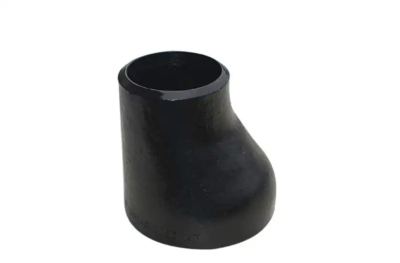
An eccentric reducer is one where the two ends are offset from one another and the center lines are not concentric. One side of the reducer might be left flush while the opposing side makes the transition. This results in an offset that is significant for dimensional inspection and pipe arrangement.
The choice of eccentric reducer is typically determined by the position of the pipe, not only the change in pipe size. In horizontal pipework, the engineer may specify flat-top or flat-bottom arrangements, depending on the service. For example, a flat bottom may be desirable in certain liquid services where it is necessary to minimize low spots and buildup of liquid, while a flat-top arrangement may be chosen in other services where avoiding pockets of gas takes precedence. Thus, the right orientation relies on system design and process circumstances.
For example, a design may specify an eccentric reducer NPS 8 x NPS 6 with an offset specified. The two nominal diameters define the linked pipes. The geometry needed is given by the drawing or the appropriate dimensional standard. The installer should not presume that all eccentric reducers with the same end diameters have the same physical orientation or installation need.
Therefore, the measurements of the reducer fittings must always be read along with the pipe plan. An erroneously placed reducer, even with the right end sizes, might result from a lack of understanding of the eccentric orientation.

How to Read a Reducer Dimension Drawing?
A reducer drawing usually contains more information than a simple product description. Understanding what each value represents makes it easier to verify a quotation, purchase order, fabrication drawing, or inspection report.
Start with NPS or DN and the two end sizes
The first values to identify are the sizes of the large and small ends. A designation such as NPS 10 × NPS 6 means that the fitting transitions between nominal 10-inch and nominal 6-inch pipe sizes.
In metric documentation, the corresponding designation may use DN rather than NPS. NPS and DN should not be treated as interchangeable numbers without checking the relevant standard because their designation systems are different.
The important point is that the reducer's nominal size describes its connection to the piping system; it does not necessarily equal the measured outside diameter. Actual outside diameter and wall thickness should be taken from the relevant pipe and fitting standards.
Check the Overall Length Before Fabrication
The overall length is especially important when a reducer is being installed into an existing line or incorporated into a prefabricated spool. If the actual fitting length differs from the value used in the piping layout, the downstream pipe dimensions may no longer match the fabrication drawing.
For this reason, engineers should use the dimensional table or approved manufacturer drawing rather than estimating the length from the apparent cone shape. ASME B16.9 specifically addresses overall dimensions and tolerances for factory-made wrought buttwelding fittings, making the applicable standard an important reference when the fitting falls within its scope.
Separate Nominal Size From Wall Thickness
A common mistake is assuming that the reducer's size designation also tells you its wall thickness. It does not.
A specification may identify a reducer by its end sizes and then separately state the required reducer fitting dimensions, schedule, wall thickness, or fitting specification. For example, NPS 6 × NPS 4, Sch 40, communicates more information than simply NPS 6 × NPS 4.
Wall thickness is relevant to pressure capability, welding preparation, dimensional compatibility, and the relationship between the fitting and the connected pipe. In actual procurement, the fitting specification and material standard should be reviewed alongside the dimensional requirement.
Confirm the End Preparation and Material Specification
A dimensional check should not stop at length and diameter. The ends of a butt-weld reducer need the correct preparation for welding, while other reducer types may use threaded, socket-weld, or flanged connections.
Material identification is equally important. Carbon steel, stainless steel, and alloy steel reducers can have different material specifications and service limitations. The correct material therefore depends on temperature, pressure, corrosion conditions, process fluid, welding requirements, and the project specification.
For example, a dimensional drawing may show the same nominal reducer size for several material grades, but that does not mean the products are interchangeable in every application. Dimensional compatibility and material compatibility are separate checks.
Why Material and Manufacturing Tolerances Matter?
The dimensions shown on a drawing represent a controlled specification, not necessarily an infinitely precise physical value. Manufacturing processes introduce tolerances, and these tolerances need to be considered when the reducer is fabricated, inspected, or installed.
Wall Thickness Is More Than a Dimensional Detail
Wall thickness affects more than the apparent strength of a reducer. It also influences the transition between the reducer and the connected pipe and can affect welding preparation and fit-up.
When a project requires a particular wall thickness, the manufacturer should produce and inspect the fitting according to the applicable specification. Engineers should not select a reducer solely because its nominal end sizes match the pipe. The fitting's material, wall requirement, pressure-temperature conditions, and governing standard all need to be consistent with the piping specification.
It is also important to distinguish between nominal wall thickness and the actual measured thickness at an individual location. Inspection requirements and allowable tolerances determine how the measured value should be evaluated.
Temperature Can Affect Dimensional Control
Thermal expansion becomes relevant when a reducer operates at elevated temperatures or when components made from different materials are joined in the same system. The fitting itself is not normally selected by simply adding a thermal expansion value to its catalog dimensions, but the broader piping design needs to account for thermal movement.
This is particularly important in long piping runs, high-temperature process systems, and installations where thermal expansion can transmit loads to connected equipment. The reducer is one component within that system, so its dimensions need to work with the overall piping arrangement rather than being evaluated in isolation.
Manufacturing Tolerances Should Be Read Alongside Nominal Dimensions
A drawing dimension and an inspection result are not necessarily expected to be identical to the last decimal place. Standards establish dimensional tolerances, while project specifications may impose additional requirements.
For this reason, a dimensional inspection should compare the measured fitting against the correct standard and purchase specification. If a reducer is being supplied for a critical project, the inspection documentation should clearly identify the fitting size, material, applicable standard, heat or batch traceability where required, and relevant dimensional results.
This approach provides much stronger quality evidence than simply stating that the reducer fitting dimensions are “accurately manufactured.”
Selecting the Right Reducer for the Piping System
Dimensions are only useful when they correspond to the actual needs of the system. A reducer with matching nominal sizes can still be unsuitable if its geometry, material, wall thickness, or connection details do not fit the application.
Consider Flow Direction and Piping Orientation
The change in diameter through a reducer influences the velocity of the fluid and the pressure behavior of the system. A gradual transition is generally preferable to an abrupt change when the system design calls for controlled flow behavior, but the appropriate geometry depends on the service and process design.
For eccentric reducers, orientation is particularly important. The designer should specify whether the reducer needs to be installed flat-side-up or flat-side-down when that detail affects drainage, venting, or process behavior. Leaving the orientation undefined can create problems during fabrication or field installation.
Match the Reducer to the Connected Pipe
The reducer needs to match the connected pipe in more than nominal size. The pipe outside diameter, wall thickness, material, weld-end preparation, and applicable dimensional standard all need to be compatible.
For example, two pipes may both be described by the same nominal size while having different wall thicknesses. A reducer selected without checking the actual pipe specification may therefore create a mismatch during fit-up.
This is especially important for prefabricated piping spools. The reducer's overall length and end dimensions affect the calculated pipe cut lengths, so even a relatively small dimensional discrepancy can require field modification.
Leave Installation and Maintenance Space
A reducer may be physically compatible with the pipe but still difficult to install if there is insufficient clearance around the fitting. This matters in pipe racks, equipment connections, compact process skids, and areas where welding access is restricted.
During layout, the engineer should consider the reducer's actual length, weld access, nearby valves and flanges, support locations, insulation requirements, and inspection access. A dimension that looks minor on a product sheet can become significant when several fittings are installed close together.
Common Mistakes When Checking Reducer Fitting Dimensions
One of the most common mistakes is using a generic online dimension table without checking the applicable standard. Different fitting standards and connection types can use different dimensional requirements, so a value copied from an unrelated table may not apply to the fitting being purchased.
Another common mistake is treating NPS as the actual outside diameter. NPS is a nominal pipe-size designation, and the actual outside diameter must be checked against the relevant pipe standard.
It is also risky to specify only the large and small end sizes when requesting a quotation. A supplier may still need the fitting type, material grade, wall thickness or schedule, standard, end preparation, quantity, and any special inspection requirements before the product can be quoted accurately.
Eccentric reducers present another potential source of error. The buyer should state the required orientation when the piping arrangement depends on a flat top or flat bottom. Otherwise, the fitting may arrive with the correct nominal dimensions but an unsuitable orientation for the intended installation.
Finally, dimensional accuracy should not be evaluated separately from documentation. For industrial projects, a buyer may need material certificates, dimensional inspection records, NDT reports, marking information, or other quality documents depending on the project requirements. A complete procurement specification therefore provides a much clearer basis for acceptance than a size designation alone.
Conclusion
Understanding reducer fitting dimensions is not simply a matter of knowing the large and small pipe sizes. A reliable dimensional check starts with the reducer type and nominal sizes, then moves to overall length, wall thickness, end preparation, material specification, tolerances, and installation orientation. Concentric and eccentric reducers serve different layout requirements, and the correct choice depends on how the piping system is designed rather than on size alone.
For engineers, fabricators, and buyers, the most reliable approach is to read the reducer together with the applicable dimensional standard, piping drawing, pipe specification, and purchase requirements. ASME B16.9-2024, for example, provides dimensional and tolerance requirements for factory-made wrought buttwelding fittings within its scope, so the current applicable edition should be confirmed rather than relying on an old table or an unverified online dimension.
Oudi: A Reliable Source for Industrial Pipe Reducers
Cangzhou Oudi Pipe Manufacture Co., Ltd. has manufactured pipe fittings since 1998 and operates in Mengcun, Hebei, one of China's established pipe-fitting manufacturing centers. The company states that its facility covers 66,600 square meters and has an annual production capacity of 16,000 tons. Its product range includes carbon steel, stainless steel, and alloy steel pipe fittings manufactured for American, Japanese, German, and British standards.
For buyers comparing reducer suppliers, manufacturing capability is only one part of the evaluation. Reducer fitting dimensions, dimensional control, material traceability, inspection procedures, applicable standards, documentation, and the ability to handle project-specific requirements are equally important. Oudi's current company information highlights ISO 9001 quality management, NDT and dimensional inspection capabilities, OEM/ODM services, and supply to international markets.
When requesting a quotation, providing the reducer type, NPS or DN sizes, material grade, wall thickness or schedule, applicable standard, quantity, and any special inspection requirements gives the manufacturer a much clearer technical basis for pricing and production. This also reduces the risk of receiving a fitting that has the correct nominal size but does not match the actual requirements of the piping system. Send an email to oudi-04@oudiguandao.com if you have any questions or would like additional information.
References
1. ASME B16.9-2018: Factory-Made Wrought Buttwelding Fittings
2. Nayyar, M. L. (2000). Piping Handbook, 7th Edition. McGraw-Hill Professional
3. Smith, P. (2018). Piping Materials Guide: Selection and Applications. Elsevier
4. ASTM A234 / A234M - 19: Standard Specification for Piping Fittings of Wrought Carbon Steel and Alloy Steel for Moderate and High-Temperature Service
5. Antaki, G. A. (2003). Piping and Pipeline Engineering: Design, Construction, Maintenance, Integrity, and Repair. CRC Press
6. Kannappan, S. (2008). Introduction to Pipe Stress Analysis. Wiley

Need help finding the right solution with our experts. Please contact us.

SINCE 1998 Your Reliable Pipeline Manufacturer