Pipe Reducer Size Chart: From DN15 to DN600 Explained
If you need to connect two pipes with different nominal sizes, a reducer is one of the most common fittings used in the piping system. The challenge is that choosing a reducer is not simply a matter of matching one DN number to another. The fitting must also suit the pipe outside diameters, end-to-end dimensions, wall thickness, material, connection method, and applicable manufacturing standard. For engineers, contractors, and purchasing teams, pipe reducer size charts provide a practical starting point for checking these dimensions before a fitting is ordered or installed. They are especially beneficial for a project with many pipe diameters, such as DN15, DN25, DN50, DN100, DN200, or even bigger lines to DN600. In this article, we will explain how to interpret reducer dimensions, the relationship between DN and NPS, whether to use concentric or eccentric reducers, and what you should check before choosing a reducer for an industrial plumbing system.
Understanding What a Pipe Reducer Size Chart Actually Tells You
A reducer is a device that reduces the pipe size from one end to the other end of a piping system. One end has a bigger nominal size and the other a smaller nominal size, enabling the system to transition from one pipe diameter to another without the need for a lot of different fittings.
A size chart often contains dimensional data and not a comprehensive engineering design document. Information may include nominal pipe size, outer diameters at the ends, end-to-end length, wall thickness or schedule references, and dimensional tolerances as appropriate to the standard and manufacturer.
For instance, ASME B16.9 deals with wrought factory-made butt-welding fittings, including reducers, and their dimensions, tolerances, ratings, testing, and labeling. The current ASME listing specifies that the standard is applicable for NPS 1/2 through NPS 48, i.e., DN15 through DN1200.
That difference is important since a reducer chart is not a pressure rating table to be used in isolation. The nominal size alone does not guarantee an appropriate pressure design. The material grade, wall thickness, operating temperature, design pressure, corrosion allowance, manufacturing standard, and the requirements of the piping code must be taken into account.
How DN and NPS Work in Reducer Dimensions?
DN is a nominal designation, not the measured pipe diameter
DN is a notional designation and not a measured pipe diameter. DN, or nominal diameter, is used extensively in international pipeline standards. A DN number does not refer to the precise internal or exterior diameter of the pipe but its notional size.
This is why a DN50 pipe should not be thought of as a true 50 mm outer diameter. The exact outer diameter will be determined by the dimensional system and the pipe standard it applies to.
Nominal pipe size, or NPS, is the typical term for pipe size in North American piping requirements. DN and NPS are connected, yet they are not simple mathematical conversions. For example, DN15 is NPS 1/2, DN25 is NPS 1, and DN50 is NPS 2.
Therefore, when reading a reducer chart, it is best to accept DN and NPS as standardized nominal designations and then validate the actual outer diameter from the applicable pipe and fitting standard.

The large end and small end must both be checked
A reducer is identified by two nominal pipe sizes. A DN100 × DN50 reducer, for example, connects a DN100 line to a DN50 line.
The larger connection is normally referred to as the large end, while the smaller connection is the small end. Both dimensions matter because the fitting must match the pipes being joined.
This becomes particularly important when purchasing reducers for an existing system. If the nominal size is copied incorrectly from a drawing or equipment connection, the fitting may appear close to the required size while still being incompatible with the actual pipe dimensions.
A reliable selection process therefore starts with the two pipe sizes and then uses pipe reducer size charts to confirm their corresponding outside diameters and connection requirements.
Reading the Main Dimensions in a Reducer Chart
Outside diameter is more useful than DN alone
One of the most important pieces of information in a reducer chart is the outside diameter at each end. This is especially relevant for butt-welding fittings because the fitting ends must align with the pipe dimensions used in the project.
ASME B16.9 reducer tables, for example, identify the nominal pipe size, outside diameter at the large end, outside diameter at the small end, and end-to-end dimension H. For a small reducer such as NPS 1 × 1/2, the listed outside diameters are 33.4 mm and 21.3 mm, with an end-to-end dimension of 51 mm.
The practical lesson is simple: do not select a reducer from DN alone. The actual pipe OD and fitting dimensional standard should be checked before fabrication or installation.
End-to-end length affects installation space
The end-to-end dimension determines how much axial space the reducer occupies between the two connecting pipes.
This measurement matters when a reducer is being installed into an existing pipeline because changing the fitting length can affect spool dimensions, pipe supports, equipment connections, and the available installation space.
For standard butt-welding reducers, the end-to-end dimension is normally defined by the applicable fitting standard and nominal size combination. ASME B16.9 dimension tables provide these values for reducer combinations, including larger sizes.
During fabrication, the reducer length should therefore be checked against the piping drawing rather than estimated from the diameter difference.
Wall thickness and schedule require a separate check
Schedule is commonly used to identify pipe wall thickness. Typical designations include Schedule 10, Schedule 40, Schedule 80, and Schedule 160, although the available schedules depend on the pipe size, material, and applicable specification.
A higher schedule generally represents a thicker nominal wall within a particular dimensional system, but it should not be described simply as meaning that the fitting is automatically “stronger” in every application.
The reducer needs to be compatible with the connected pipe wall thickness and the project's design requirements. The pressure-temperature conditions, material grade, corrosion allowance, fabrication method, and applicable piping code may all influence the final specification.
For that reason, a size chart should be used together with the relevant material and piping standards rather than as the only document used for pressure design.
Choosing Between Concentric and Eccentric Reducers
Concentric reducers keep the centerline aligned
A concentric reducer has a common centerline at both ends. As the diameter changes, the fitting remains centered around the same axis.
This configuration is often suitable for vertical piping and for systems where maintaining a common pipe centerline is desirable. Standard dimensional references show that concentric reducers have defined end-to-end dimensions for each nominal size combination.
For example, a DN100 × DN50 transition can use a concentric configuration when the connected pipework is designed around a common centerline.
The choice should still be based on the overall piping arrangement rather than on size alone.
Eccentric reducers solve different layout problems
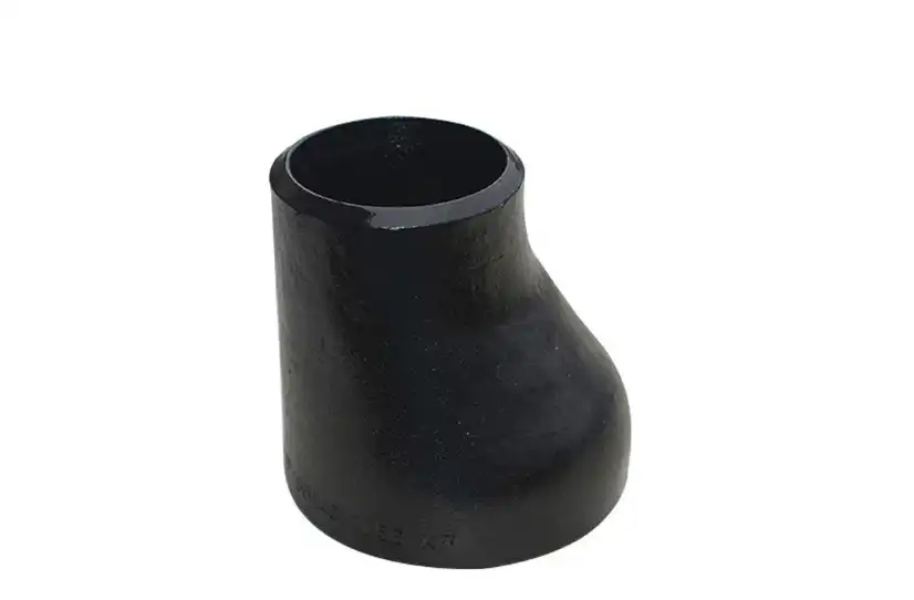
An eccentric reducer has offset centerlines, creating a flat side on one portion of the fitting. This geometry can be useful in horizontal piping where maintaining the desired elevation of the pipe centerline or avoiding unwanted liquid or vapor pockets is important.
For pump suction piping, orientation is particularly important. An eccentric reducer may be installed with the appropriate flat-side orientation to reduce the risk of vapor accumulation, depending on the system design. Pipe reducer size charts can help engineers verify the applicable dimensions when selecting the required reducer size, while reference dimensional data shows that eccentric reducers use the same standard end-to-end dimensions as corresponding concentric reducers for many ASME B16.9 size combinations, while their geometry is different.
The decision between concentric and eccentric construction should therefore come from the piping layout, process conditions, drainage requirements, and equipment arrangement.
What DN15 to DN600 Means in Practical Applications?
DN15 to DN50 for compact piping systems
The smaller range from DN15 through DN50 is common in utility piping, building services, instrumentation-related connections, HVAC equipment, and smaller process lines.
At this scale, space is often limited, so the reducer's overall length and connection type can have a noticeable effect on installation. Threaded reducers may be used in some low-pressure applications, while butt-welding or other connection methods are selected when the project specification requires them.
For procurement, it is useful to confirm whether the connection is threaded, socket-weld, butt-weld, or another configuration before relying on a dimensional chart.
DN65 to DN200 for process and utility piping
The DN65 through DN200 range covers many medium-sized industrial lines. These sizes are frequently encountered in water treatment, chemical processing, manufacturing facilities, HVAC plants, utility networks, and other process systems.
At these sizes, reducer selection becomes more closely tied to the piping specification. Material grade, schedule, welding requirements, corrosion conditions, and operating pressure can all affect the final fitting specification.
For example, a DN150 × DN100 reducer may have the correct nominal size combination but still be unsuitable if its material or wall-thickness specification does not match the connected pipework.
This is why pipe reducer size charts are most useful when they are read together with the project's piping class or line specification.
DN250 to DN600 for large industrial pipelines
Reducers from DN250 through DN600 are commonly associated with larger water, energy, chemical, petrochemical, and industrial infrastructure.
At this scale, dimensional accuracy becomes particularly important because a fitting may be incorporated into a prefabricated spool or connected directly to large valves, pumps, vessels, or other equipment.
Large reducers can also have significant weight, so the design team may need to consider support arrangements and handling requirements during installation. The fitting dimension itself is only one part of the engineering decision.
The applicable manufacturing standard should also be confirmed. ASME B16.9 extends considerably beyond DN600, so DN600 is not the upper dimensional limit of that standard. The article's DN15–DN600 range is therefore better understood as a practical project range rather than the full range covered by ASME B16.9.
A Better Way to Use Pipe Reducer Size Charts
The most reliable approach is to work from the pipe specification toward the fitting rather than starting with a reducer size and trying to make the rest of the system fit.
First, identify the large and small pipe sizes. Then confirm whether the project uses DN, NPS, or both. After that, check the actual outside diameters and the required end-to-end dimension.
The reducer type should then be selected according to the piping layout. A concentric reducer may be appropriate where the centerline should remain aligned, while an eccentric reducer may be preferred when the piping arrangement requires an offset geometry.
The material and wall-thickness requirements should be checked next. Carbon steel, stainless steel, and alloy steel reducers are not interchangeable simply because their nominal dimensions are similar. The material needs to be compatible with the fluid, temperature, pressure, corrosion environment, and project specification.
Finally, confirm the applicable manufacturing standard and inspection requirements. For butt-welding fittings, ASME B16.9 is one commonly referenced dimensional and manufacturing standard, while pipe reducer size charts can help verify the dimensions of reducers against the specified requirements. Other projects may specify different standards depending on region, application, and piping class. The current ASME description confirms that B16.9 covers overall dimensions, tolerances, ratings, testing, and markings for factory-made wrought butt-welding fittings.
Common Mistakes When Selecting a Reducer
One common mistake is assuming that the DN number represents the actual outside diameter. It does not. The nominal designation must be checked against the dimensional standard and the pipe specification.
Another mistake is choosing a reducer based only on the large and small nominal sizes. Two reducers with the same nominal size combination may differ in material, wall thickness, connection type, standard, or configuration.
It is also easy to confuse concentric and eccentric reducers. Their dimensional envelopes may be similar, but their geometry serves different piping arrangements. Installing the wrong configuration can create problems with elevation, drainage, pump suction conditions, or equipment alignment.
A further issue is treating a size chart as a pressure-rating document. Dimensions, material properties, wall thickness, design pressure, temperature, and code requirements should be evaluated together. A chart can confirm whether the fitting has the required dimensions, but it should not replace the project's engineering calculations or piping specification.
What to Confirm Before Ordering a DN15–DN600 Reducer?
Before placing an order, the fitting description should contain enough information for the manufacturer to identify the required product without relying on assumptions. The large-end and small-end sizes should be stated clearly, followed by the reducer type, material grade, wall thickness or schedule, connection type, and applicable standard.
For a butt-welding reducer, the project may also require details concerning welding bevels, inspection, testing, marking, and certification. These requirements should be taken from the project specification and applicable standard rather than inferred from the nominal size.
This approach also makes communication between engineers, purchasing teams, fabricators, and suppliers much easier. A specification such as “DN200 × DN100 eccentric reducer, carbon steel, specified schedule, butt-weld ends, applicable project standard” provides much more useful information than simply requesting a “DN200 reducer.”
Conclusion
The Pipe Reducer Size Chart is a useful reference for understanding how reducers connect different pipe sizes, but the chart should be treated as part of the selection process rather than the entire design basis. From DN15 to DN600, the correct fitting depends on more than nominal diameter. Outside diameter, end-to-end length, reducer configuration, wall thickness, material, connection type, and applicable standards all need to be considered together.
For engineers and purchasing teams, pipe reducer size charts are most valuable when they are used to verify dimensions against the actual piping specification. Once the size combination and fitting type are confirmed, the remaining checks can be made against the material, schedule, operating conditions, and relevant manufacturing standard. This approach reduces ordering errors, avoids installation conflicts, and gives project teams a clearer basis for selecting reducers that fit the piping system as designed.
To learn more about our premium pipe fittings, including reducers, get in touch with us at oudi-04@oudiguandao.com. No. 1 in China for carbon steel pipe fittings, valves, and flanges since 1998 is Cangzhou Oudi Pipe Manufacture Co., Ltd. Our cutting-edge fabricating offices, broad specialized information, and immovable devotion to quality have earned us the confidence of over 300 clients in 40 nations. Our broad product line permits us to serve an assortment of segments, and we are committed to giving our clients the finest arrangements and administrations conceivable. The chemical, petroleum, natural gas, conservation of water, and building industries are only a few examples.
References
1. Smith, J. (2020). Understanding Pipe Reducer Sizing: A Comprehensive Guide. Journal of Piping Engineering, 45(2), 78-92.
2. Johnson, A. & Brown, R. (2019). Industrial Piping Systems: Design and Selection of Fittings. New York: Engineering Press.
3. Thompson, L. (2021). Advances in Pipe Reducer Technology for Improved Flow Characteristics. International Journal of Fluid Dynamics, 33(4), 412-428.
4. Wilson, M. (2018). Pipe Fitting Standards and Specifications: A Global Perspective. London: Technical Publications Ltd.
5. Garcia, C. et al. (2022). Material Selection for Pipe Reducers in Corrosive Environments. Corrosion Science and Technology, 57(3), 201-215.
6. Anderson, P. (2020). Optimizing Piping System Design: The Role of Proper Reducer Selection. Engineering Design Quarterly, 28(1), 45-59.

Need help finding the right solution with our experts. Please contact us.

SINCE 1998 Your Reliable Pipeline Manufacturer