How to Match Carbon Steel Elbows with Tees, Reducers, and Flanges?
Selecting the right combination of carbon steel elbows, tees, reducers, and flanges is not simply a matter of choosing components with the same nominal size. A reliable pipeline connection is dependent on several interrelated criteria such as pipe size, wall thickness, fitting dimensions, material grade, pressure rating, connection type, and service circumstances. If these parameters are not examined before installation, a fitting may seem to be a physical match but yet cause difficulties with welding, flow, sealing, or pressure performance. The most practical method for engineers, contractors, and buying teams is to regard the pipe assembly as one integrated system as opposed to choosing each fitting separately. The elbow sets the direction of the line, the tee produces a branch, the reducer alters the flow diameter, and the flange offers a bolted connection to another component. Their size and specifications consequently have to be in harmony right from the start. This tutorial discusses how to match these components and what should be evaluated before manufacture, installation, and final testing.
Start with the Piping Dimensions Before Selecting Fittings
Match NPS Without Assuming Every Dimension Is Identical
One of the first criteria that you should verify when choosing carbon steel elbows and associated fittings is nominal pipe size, or NPS. The NPS defines the nominal size of the pipe system but does not independently define all the dimensional details necessary for a successful connection. The wall thickness, outer diameter, fitting design, and appropriate dimensional standards are yet to be determined.
For example, a 4-inch elbow for a 4-inch pipe system will generally be chosen around the same nominal pipe size, but the tee or reducer it is linked to may have a different design. A reducing tee can go 4 inches with a 2-inch branch. A reducer can go from 4 inches to 3 inches. Thus, the right selection relies on the position of each component on the line and not just on the selection of fits with the same numbers.
Same for the elbows of carbon steel. The size of the elbow must be such that the pipe size at either end of the elbow is met and the radius and wall thickness are suitable for the piping design. If you are buying numerous fittings for one project, you should provide the supplier full dimensional requirements, not just a broad description such as “4-inch carbon steel fittings.”
Check Schedule and Wall Thickness at Each Connection
The schedule is especially critical for butt-welding fittings to pipe. SCH40, SCH80, and other schedule designations refer to a range of wall thicknesses associated with the nominal pipe size, while actual thickness varies by size and specification. The fitting and pipe should then be tested for suitable wall thickness and weld-end specifications prior to manufacture.
A widespread misconception is that matching NPS suggests the components are ready to weld. It isn't. If the pipe and fitting wall thicknesses vary substantially, further technical consideration may be required in the welding preparation. The internal bore may also alter the flow and cause an unpleasant transition if the components are not chosen properly.
In addition to the material specification, the appropriate dimensional standard should be checked for carbon steel elbows, tees, and reducers made for butt-welding applications. The ASTM A234/A234M specification is for wrought carbon steel and alloy steel fittings for moderate and increased temperature pressure pipe and pressure vessel use. The ASME dimensional standards are for the geometry and dimensions of suitable fittings.

Coordinate Elbows with Tees and Reducers by Flow Direction
Choose the Elbow Radius According to the Piping Layout
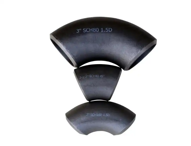
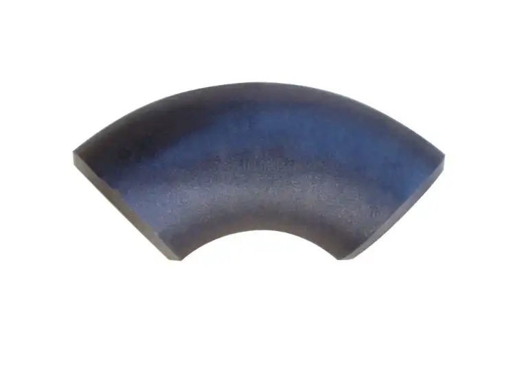
The radius of an elbow influences both the physical routing of the pipeline and the behavior of the flowing media. Long-radius elbows usually provide a smoother change of direction since the centerline radius is usually 1.5 times the normal pipe size. Short-radius elbows are made with a tighter bend and may be advantageous if room is limited for installation.
That doesn’t imply large-radius carbon steel elbows are the ideal solution for every project. Short-radius designs may be required for compact plant layouts, equipment connections, skid assemblies, or other space-constrained applications. A large radius may be used for systems where pressure loss, flow behavior, or pigging needs are significant.
The right option must thus start with the plumbing layout and service needs. The choice of elbow radius depends on available space, flow characteristics, operational pressure and temperature, and project criteria. Matching the actual routing of the elbow to its routing is as critical as matching its nominal size.
Connect Tees According to the Main Run and Branch
A tee adjusts the flow of a plumbing system. It splits or joins flow. When an elbow is built in the vicinity of a tee, the orientation of both parts must be addressed in conjunction. The tee sets the direction of the main run and branch, while the elbow adjusts the direction of one part of the line.
Poor orientation might result in needless pipe offsets, additional welds, or increased load on associated equipment. It may also complicate maintenance when valves, instruments, or other components are located near the branch.
Hence, the connection should be designed from the centerline of the pipe and not from the outside form of the fittings. A sketch or 3D model may also be beneficial to validate the orientation before fabricating. Combining carbon steel elbows with tees in a sophisticated routing system might result in expensive field changes later on. Verifying the center-to-end dimensions of the fittings can help.
Use Reducers Only When the Diameter Transition Is Correct
When the pipe changes from one nominal size to another, a reducer is needed. The interaction with an elbow is of particular importance, as the arrangement and orientation of the components might affect the available installation space and the flow transition.
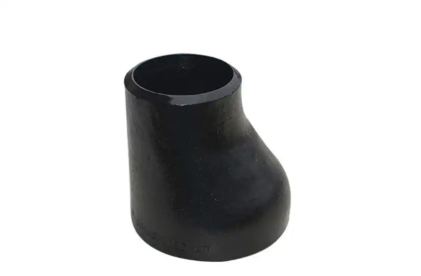
The selection of a reducer should be based on the pipe diameters in the upstream and downstream, not on the entire length. Concentric reducers are most often employed when the centerline has to stay in line, while eccentric reducers may be used where it is vital to maintain a certain pipe elevation or avoid undesirable accumulation.
The reducer should be suitable with the material, wall thickness, end preparation, and relevant dimensional criteria of the linked elbow and tee. For example, if you have a 6-inch pipe that goes down to 4 inches before going through an elbow, the design should specify whether the reducer is before or after the elbow and if the resultant geometry fits the planned routing. It is simpler and less costly to make such selections at the design stage than at the installation stage.
Match Flanges by Rating, Facing, and Connection Details
Do Not Treat Flange Schedule as the Main Matching Criterion
Flanges require a different matching approach from butt-welding fittings. Although pipe size remains important, flange compatibility also depends on pressure class, facing type, bore, material, bolting, and the connection configuration.
ASME B16.5 covers pipe flanges and flanged fittings from NPS 1/2 through NPS 24 and includes requirements related to pressure-temperature ratings, materials, dimensions, tolerances, marking, and testing.
As a result, saying that an elbow and flange must have the “same schedule” is an oversimplification. A flanged connection should instead be evaluated according to the flange type and the piping design. For a weld-neck flange, for instance, the bore and welding end need to be compatible with the pipe or fitting being joined. The flange pressure class must also be suitable for the operating conditions.
This distinction is important during procurement because two components can have the same NPS but still be unsuitable for one another if their pressure classes, facings, or connection dimensions do not correspond.
Confirm Pressure Class and Facing Before Ordering
A flange connection must be evaluated as a complete assembly, particularly when it is used with components such as carbon steel elbows. The selected flange class should be appropriate for the design pressure and temperature, while the facing should be compatible with the mating flange and gasket.
For example, a Class 150 flange should not be selected merely because the connected elbow is 4 inches in size. The project specification may require a different pressure class based on the operating conditions. Similarly, a raised-face flange and a different facing arrangement should not be mixed without confirming that the complete sealing system is appropriate.
The same attention should be given to bolt-hole dimensions and gasket selection. A correctly sized flange can still produce leakage if the mating flange, gasket, or bolting arrangement is incompatible. This is why flange information should be confirmed directly from the piping specification rather than inferred from the elbow size alone.
Keep Materials and Welding Requirements Consistent
Confirm the Fitting Material Grade Before Fabrication
Dimensional compatibility is only one part of the selection process. The material grade must also be appropriate for the service environment and consistent with the piping specification.
ASTM A234/A234M applies to wrought carbon steel and alloy steel fittings used in pressure piping and pressure vessel fabrication for moderate and elevated temperature service. The specification includes requirements associated with material properties and testing, while fittings can also be manufactured to applicable ASME or MSS dimensional standards.
A purchasing specification should therefore identify the required material grade rather than simply stating “carbon steel.” Depending on the project, the specification may need to identify a particular grade, such as ASTM A234 WPB or another material required by the applicable piping class.
Material compatibility becomes particularly important when the piping contains corrosive fluids, operates at elevated temperatures, or connects to components made from different alloys. If dissimilar metals are joined, the potential for galvanic corrosion and differences in thermal expansion should also be evaluated.
Prepare Welded Connections According to the Approved Procedure
The quality of a welded connection depends on much more than selecting an appropriate welding process. Before welding carbon steel elbows to tees, reducers, or pipe, the fabrication team should verify the material grade, wall thickness, bevel preparation, cleanliness, fit-up, and applicable welding procedure.
SMAW and GTAW may both be used for carbon steel applications, but the appropriate process depends on the project requirements and approved welding procedure. Preheating, interpass temperature, filler metal, heat input, and post-weld treatment may also be relevant depending on the material and service conditions.
The components should be properly aligned before welding rather than being forced into position with excessive external loading. A poor fit-up can introduce residual stress and make it difficult to achieve a consistent weld. Once the joint has been completed, the required inspection should be performed according to the project specification and applicable code.
Prevent Installation Problems Before They Reach the Field
Control Thermal Movement in High-Temperature Systems
Temperature changes can cause piping to expand and contract, and fittings positioned near fixed equipment can experience additional loads as the system moves. Carbon steel elbows are often located at changes in direction, which means they can become important points in the piping flexibility analysis.
A piping system exposed to substantial temperature variation should therefore be evaluated for thermal expansion before the final support arrangement is established. The solution is not necessarily to install expansion joints at every elbow. Depending on the system, flexibility may be provided through the natural geometry of the piping, appropriate guides and supports, loops, or engineered expansion devices.
The important point is that thermal movement should be considered as part of the overall piping design. Simply adding an expansion device without checking the rest of the system may transfer the problem to another connection or piece of equipment.
Consider Corrosion and Service Conditions Together
Carbon steel offers a practical combination of strength, availability, and cost for many piping applications, but its corrosion resistance depends heavily on the operating environment. Water, oxygen, chemicals, high humidity, and certain process fluids can accelerate corrosion if the material and protection system are not properly selected.
When carbon steel elbows are used in a corrosive service, the engineering team should consider the fluid composition, temperature, pressure, corrosion allowance, internal lining or coating requirements, and inspection strategy. External protection may also be necessary when the fittings are exposed to moisture or aggressive atmospheric conditions.
Connecting carbon steel components to stainless steel or other dissimilar metals requires additional consideration. The joint itself may be mechanically compatible while still creating a corrosion concern under certain environmental conditions. Material selection should therefore be based on the complete service environment rather than on the fitting alone.
Conclusion
Coordinating carbon steel elbows with tees, reducers, and flanges requires more than matching nominal pipe sizes. The successful connection of these components depends on understanding how dimensions, wall thickness, bend radius, material grade, pressure class, flange facing, welding requirements, and operating conditions interact within the same piping system.
The most reliable approach is to begin with the piping design and then select each component according to its actual position and function. Elbows should be chosen according to the required direction and radius, tees should correspond to the main run and branch configuration, and reducers should provide the correct transition between pipe sizes. Flanges require additional attention to pressure class, facing, bore, bolting, and gasket compatibility rather than being treated as another fitting with the same schedule.
Material and fabrication requirements should also be confirmed before installation. ASTM A234/A234M provides requirements for applicable wrought carbon steel and alloy steel fittings, while ASME standards address the dimensions and requirements of different fitting and flange categories. When these requirements are considered together, the result is a piping assembly that is easier to fabricate, inspect, maintain, and operate.
For purchasing teams, the final check should always go beyond the product name. Confirm the size, schedule or wall thickness where applicable, material grade, dimensional standard, flange class and facing, connection type, inspection requirements, and documentation before placing the order. Choosing compatible carbon steel elbows and related fittings at the procurement stage can prevent welding problems, field modifications, leakage, and unnecessary project delays later.
For master help with carbon steel elbows and other channeling components, do not delay; reach out to Cangzhou Oudi Pipe Make Co., Ltd. at oudi-04@oudiguandao.com. Our group of experts is prepared to offer assistance to help you accomplish what comes about in your channeling ventures.
FAQ
1. What is the difference between long-radius and short-radius carbon steel elbows?
Long radius elbows have a centerline radius equal to 1.5 times the nominal pipe size, while short radius elbows have a centerline radius equal to the nominal pipe size. Long-radius elbows generally offer smoother flow and lower pressure drop.
2. How do I ensure proper alignment when installing carbon steel elbows?
Use a level or laser alignment tool to verify correct positioning. Carefully measure and mark pipe sections before installation, and pay attention to the orientation of reducing elbows and tee connections.
3. What welding techniques are recommended for carbon steel elbows?
Common welding techniques for carbon steel elbows include shielded metal arc welding (SMAW) and gas tungsten arc welding (GTAW). The choice depends on material thickness and project requirements.
4. How can I prevent corrosion in carbon steel elbows?
Use protective coatings or linings, consider alternative materials for highly corrosive environments, and implement regular inspection and maintenance programs.
References
1. ASME B31.3: Process Piping. American Society of Mechanical Engineers, 2018.
2. Nayyar, M. L. Piping Handbook. 7th ed., McGraw-Hill, 2000.
3. Smith, P. Piping Materials Guide. Elsevier, 2005.
4. ASTM A234 / A234M - 19: Standard Specification for Piping Fittings of Wrought Carbon Steel and Alloy Steel for Moderate and High Temperature Service. ASTM International, 2019.
5. Antaki, G. A. Piping and Pipeline Engineering: Design, Construction, Maintenance, Integrity, and Repair. CRC Press, 2003.
6. Kannappan, S. Introduction to Pipe Stress Analysis. Wiley, 1986.

Need help finding the right solution with our experts. Please contact us.

SINCE 1998 Your Reliable Pipeline Manufacturer