How to Read a Pipe Reducer Size Chart: A Step-by-Step Guide
Having the ability to accurately read a pipe reducer size chart is essential to making an accurate selection for your industrial plumbing system. The chart will normally display the diameters of the inlet and outlet in either millimeters or inches, as well as the requirements for the wall thickness and the amount of dimensional tolerance. In this table, each row represents a different reducer configuration, and each column displays the relevant measurements for length, weight, and pressure ratings. By gaining an understanding of these criteria, you will be able to select the appropriate pipe reducer to meet the requirements of your particular application. This is true regardless of whether you are working with concentric or eccentric configurations in oil, chemical, or water conservation projects.

Understanding Basic Pipe Reducer Terminology
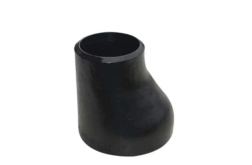
Pipe reducers are transition fittings that establish connections between pipes of varying diameters that are contained inside a piping system. These vital components ensure that the flow is continuous while simultaneously adjusting to the different pipe sizes that are present in industrial systems. The language that pertains to reducers encompasses several fundamental ideas that specialists are required to have a firm grasp on.
The wider opening that is responsible for receiving fluid from the pipe section that is located upstream is referred to as the inlet diameter. On the other hand, the outlet diameter serves as a representation of the smaller hole that is connected to the piping further downstream. This link between size and pressure determines the reduction ratio, which in turn influences the flow characteristics and pressure dynamics inside your system.
When it comes to size charts, measurements of wall thickness are typically presented as schedule numbers or direct dimensional values. Utilizing these criteria, the pressure rating of the reducer as well as its structural integrity under operational conditions are determined. The grades of the material also have an effect on performance; for example, carbon steel, stainless steel, and alloy steel are all available for use in a variety of applications.
The designations of nominal pipe size (NPS) contribute to the standardization of measurements across many industrial standards. Understanding NPS conversions is essential for ensuring appropriate component selection for worldwide projects, regardless of whether you are working with any of the following standards: ANSI, JIS, DIN, or BS.

Decoding Size Chart Dimensions
A thorough interpretation is required when interpreting size charts because they give dimension data in ordered formats. Among the key metrics is the overall length, which has an impact on the amount of space that is required for installation and the thermal expansion variables to be considered. The measurements from center to end are helpful in determining the location of fittings within preexisting piping layouts.
In most cases, measurements of diameter are presented in the form of both nominal and actual values. The nominal dimensions provide generic size categories, but the actual measurements provide precise specifications that can be used for manufacturing and quality control purposes. In the context of working with applications that require tight tolerances, such as those found in chemical processing or power production facilities, these distinctions become essential.
When working on large-scale projects, engineers are able to calculate the structural support needs and transportation costs with the assistance of weight parameters that are shown on charts. In many cases, heavier reducers are indicative of thicker walls and higher pressure ratings, making them suitable for use in tough industrial applications.
During the manufacturing process, permitted dimensional differences are indicated by manufacturing tolerances that are displayed on charts. When procurement personnel have a better understanding of these ranges, they are better able to evaluate quality standards and maintain compatibility with current pipe reducer installations.

Reading Pressure and Temperature Ratings
At particular temperatures, the pressure ratings that are displayed on reducer charts correspond to the maximum working pressures that are permitted. The material qualities, wall thickness, and manufacturing procedures that are utilized in the production process all have an impact on these values. Pressure ratings that are higher than those of normal water distribution systems are frequently required for applications in the chemical industry.
Temperature ratings provide an indication of the safe operating range appropriate for a variety of materials and setups. Reducers made of stainless steel are often able to withstand higher temperatures than their carbon steel counterparts, which makes them acceptable for use in steam systems and chemical processes that operate at high temperatures.
There are derating factors that are created as a result of the interaction between pressure and temperature. These derating factors limit the permissible pressures as temperatures rise. There are many pressure ratings for different temperature ranges that can be included in size charts. These pressure ratings can assist engineers in selecting components that are suitable for a variety of operating circumstances.
There are operational margins that are provided by safety factors that are included in pressure ratings. These buffers are for unexpected pressure surges or heat cycling. Having an understanding of these margins helps to prevent problems in the system and assures the long-term reliability of applications that are most important applications.
Identifying Connection Types and Standards
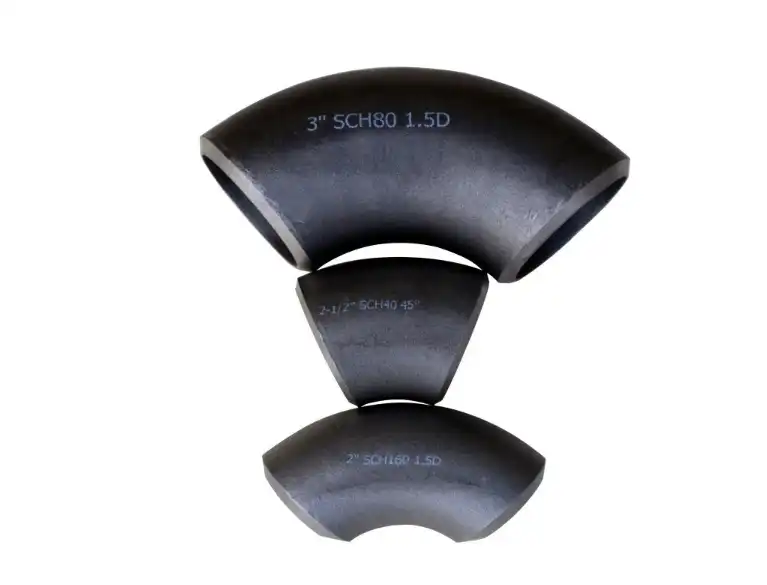
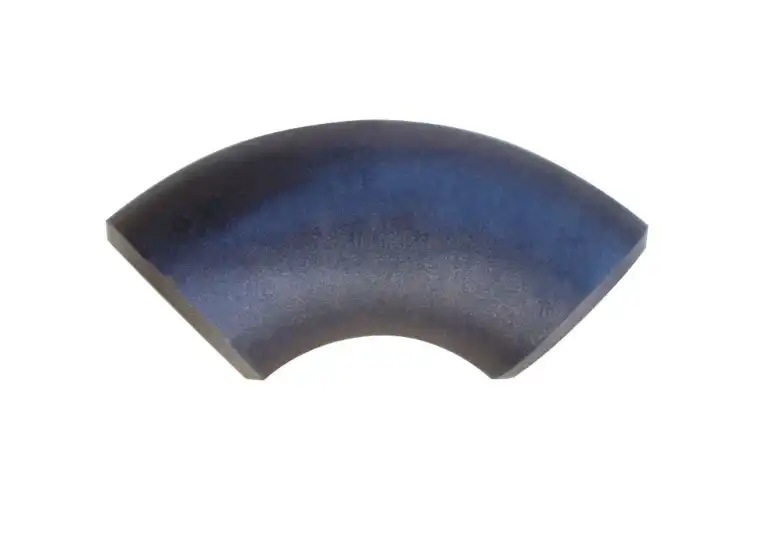
On size charts, the connection specifications specify how reducers are attached to the components of the piping that are adjacent to them. However, butt weld connections provide the strongest joints and are highly effective in applications that involve significant pressure. Installation in systems with a smaller diameter is made simpler by the availability of socket weld solutions.
Despite the fact that threaded connections are used in industrial applications less frequently, they offer a number of benefits, including access for maintenance and temporary installations. It is simple to disassemble flanged connections, and they are compatible with flanged piping systems that are already in place.
Conformity with international standards has an impact on the accuracy of dimensions and the quality assurance process. The ANSI standards are the most widely used in North American markets, although DIN criteria are frequently included in European projects. The Japanese Industrial Standard (JIS) is extensively utilized in Asian markets to ensure that local production procedures are consistent.
For the purpose of ensuring that welding or connection is carried out correctly, end preparation specifications detail the machining and surface polish criteria. Although square cuts are more effective for socket connections, beveled ends make butt welding easier to do.
Material Specifications and Selection
The precise alloy composition and qualities of each reducer are identified by the material codes that are displayed on size charts. Products made of carbon steel grades such as A234 WPB offer cost-effective solutions for applications that involve moderate pressure and temperature. Stainless steel grades such as A403 WP316L provide an exceptional level of corrosion resistance for settings that are used for chemical processing.
Materials made of alloy steel are in a position to withstand the high temperatures and pressures that are present in power generation and petrochemical plants. Specialty materials like these attract higher pricing, but they give improved performance in applications that are very demanding.
Both the qualities of the material and its performance characteristics are impacted by the heat treatment requirements. Different combinations of strength and toughness can be achieved by normalized, annealed, or quenched and tempered conditions. These conditions are suited for a wide range of specific service circumstances.
Compliance with quality standards and the traceability of materials are ensured by certification criteria. The chemical composition and mechanical qualities of a product are verified by mill test certificates, while extra quality assurance is provided by third-party inspection for particularly important applications.
Step-by-Step Chart Reading Process
In order to get started, you should determine the required pipe sizes for the inlet and outflow depending on the specifications of your system design. Locate these dimensions on the size columns of the chart to reduce the number of available possibilities. Examine the pressure and temperature requirements for each size combination and compare them to the ratings that correspond to those needs.
Check that the material is compatible with the fluids used in your process and the environment in which you operate. For the purpose of preventing corrosion or contamination problems that could undermine the integrity of the system, chemical compatibility tables are helpful. When considering the various material possibilities, it is important to take into account issues such as pH levels, chloride concentration, and temperature cycling.
You should check the dimensional limitations, which include the overall length and the measurements from center to end. Ensure that there is sufficient room available for installation and access to maintenance in the future. It is important to take into account the requirements for pipe support and thermal expansion when evaluating space requirements.
It is important to verify that the manufacturing standards comply with the specifications of your project. There is a possibility that certain certifications or testing paperwork will be necessary for international projects. Make sure that the reducer you have chosen complies with all of the different codes and standards that are relevant to your application.
Common Sizing Mistakes and How to Avoid Them
Misreading nominal versus actual dimensions leads to costly installation delays and rework. Always verify which measurement system the chart uses and convert between standards when necessary. Double-check critical dimensions against your piping drawings before finalizing orders.
Overlooking pressure deration at elevated temperatures causes safety hazards and premature failures. Calculate actual operating conditions, including pressure surges and temperature spikes, to ensure adequate safety margins. Consider future operating changes that might affect system requirements.
Ignoring material compatibility requirements results in corrosion, contamination, or mechanical failures. Consult chemical compatibility references and consider long-term exposure effects. Factor in cleaning agents, startup chemicals, and emergency operating conditions when selecting materials.
Inadequate consideration of manufacturing tolerances creates installation difficulties and poor system performance. Understand how tolerance stack-up affects overall system dimensions. Specify appropriate tolerance grades for your application requirements.
Conclusion
Mastering pipe reducer size charts empowers you to make informed decisions for your industrial piping projects. Accurate chart interpretation ensures proper component selection, prevents costly mistakes, and enhances system reliability. Understanding dimensional specifications, pressure ratings, and material properties helps optimize performance while maintaining safety standards.
Professional procurement requires attention to manufacturing standards, tolerance requirements, and compatibility factors that affect long-term system operation. Taking time to verify specifications against actual operating conditions prevents future problems and reduces maintenance costs. Partnering with experienced manufacturers like Oudi provides access to technical expertise and quality assurance that support successful project completion.
Partner with Oudi for Premium Pipe Reducer Solutions
Oudi stands as your trusted pipe reducer manufacturer with over 25 years of proven expertise in industrial pipe fitting production. Our ISO 9001-certified facility delivers comprehensive reducer solutions meeting ANSI, JIS, DIN, and BS standards for global markets. With 16,000-ton annual capacity and advanced quality control systems, we ensure consistent supply chain reliability for your critical projects. Contact oudi-04@oudiguandao.com today to discuss your specific requirements.
References
1. American Society of Mechanical Engineers. "ASME B16.9: Factory-Made Wrought Buttwelding Fittings." New York: ASME Press, 2018.
2. Smith, Robert J. "Industrial Piping Systems: Design and Installation Guidelines." Engineering Publications International, 2020.
3. International Organization for Standardization. "ISO 3419: Non-alloy and Alloy Steel Butt-welding Fittings." Geneva: ISO Publications, 2019.
4. Johnson, Michael A. and Thompson, Sarah L. "Pipe Fitting Selection and Sizing Manual for Industrial Applications." Technical Press Limited, 2021.
5. European Committee for Standardization. "EN 10253: Butt-welding Pipe Fittings - Part 2: Wrought Carbon and Ferritic Alloy Steels." Brussels: CEN Publishing, 2020.
6. Williams, David R. "Pressure Vessel and Piping Codes: A Practical Reference Guide." Industrial Standards Institute, 2022.

Need help finding the right solution with our experts. Please contact us.
SINCE 1998 Your Reliable Pipeline Manufacturer